[Josh] has a series called Ham Radio Crash Course and a recent installment covers how you can grab satellite images directly from weather satellites. This used to be more of a production than it is now thanks to software defined radio (SDR). Josh also has another project using a 3D printer to make an antenna suitable for the job. You can see the video below.
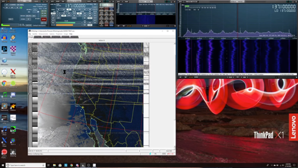
The software is the venerable WXtoImg program. This is abandonware, but the community has kept the software available. The program works on Linux, Windows, and Mac. The satellites in question operate around 137 MHz, but that’s easily in the range of even the cheap SDR dongles. [Josh] shows how to use a virtual audio cable on Windows to connect the output of the radio to the input of the WXtoImg program. Under Linux, you can do this with Pulse or Jack very easily without any extra hardware.
There’s some setup and calibration necessary for the software. You’ll also need the current orbital data and the program will tell you when you can find the next satellite passing overhead. Generally speaking you’ll want your antenna outside, which [Josh] solved by taking everything outdoors and having some lunch during the pass. It also takes some time to post-process the data into images and audio.
We know this isn’t new. But we did like [Josh’s] clear and up-to-date guide. We remember watching NOAA 15 as it started to lose its electronic mind.
Continue reading “Get Your Weather Images Straight From The Satellite”