Arduino-Controlled Coil Winder

Coil winders are a popular project because doing the deed manually can be an incredibly tedious and time consuming task. After building one such rig, [Pisces Printing] wanted to find even further time savings, and thus designed an improved, faster version.

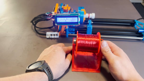
At it’s heart, it’s a straightforward design, using a linear rail and a leadscrew driven by a stepper motor. Control is via an Arduino Nano, with a few push buttons and a 16 x 2 LCD display for user feedback.

Often, completing a first build will reveal all manner of limitations and drawbacks of a design. In this case, the original winder was improved upon with faster stepper motors to cut the time it took to wind a coil. A redesigned PCB also specified a better buck converter power supply to avoid overheating issues of the initial design. A three-jaw lathe-style chuck was also 3D printed for the build to allow easy fixing of a coil bobbin.

Designing custom tools can be highly satisfying in and of itself, beyond the productivity gains they offer. Video after the break.

Continue reading “Arduino-Controlled Coil Winder”

Analog ASIC Design Built Using Digital Standard Cells

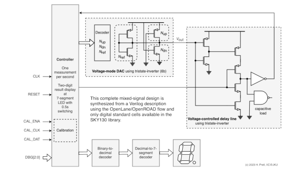
Tiny Tapeout is a way for students, hobbyists, and home gamers to get their own ASICs designs fabbed into real custom chips. Tiny Tapeout 3 was the third running, with designs mandated to be made up of simple digital standard cells. Only, a guy by the name of [Harald Pretl] found a way to make an analog circuit using these digital cells anyway.

In a video on YouTube, [Harald] gave an interview on how he was able to create a temperature sensor within the constraints of the Tiny Tapeout 3 requirements. The sensor has a range of -30 C to 120 C, albeit in a relatively crude resolution of 5 degrees C. The sensor works by timing the discharge of a pre-charged parasitic capacitor, with the discharge current being the subthreshold current of a MOSFET, which is highly dependent on temperature.  [Harald] goes deep into the details on how the design achieves its full functionality using the pre-defined digital cells available in the Tiny Tapeout 3 production run.

You can checkout a deeper breakdown of [Harald]’s design on the submission page. Meanwhile, Tiny Tapeout creator [Matt Venn] gave a great talk on the technology at Hackaday Supercon last year.

Continue reading “Analog ASIC Design Built Using Digital Standard Cells”

Looking Inside A 3D Printer Nozzle With Computed Tomography

Have you ever wondered what’s actually going on inside the hotend of your 3D printer? It doesn’t seem like much of a mystery — the filament gets melty, it gets squeezed out by the pressure of the incoming unmelty filament, and lather, rinse, repeat. Or is there perhaps more to the story?

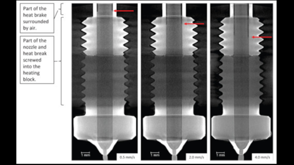
To find out, a team from the University of Stuttgart led by [Marc Kreutzbruck] took the unusual step of putting the business end of a 3D printer into a CT scanner, to get a detailed look at what’s actually going on in there. The test setup consisted of a Bondtech LGX extruder and an E3D V6 hot end mounted to a static frame. There was no need for X-Y-Z motion control during these experiments, but a load cell was added to measure extrusion force. The filament was a bit specialized — high-impact polystyrene (HIPS) mixed with a little bit of tungsten powder added (1% by volume) for better contrast to X-ray. The test system was small enough to be placed inside a micro CT scanner, which generated both 360-degree computed tomography images and 2D radiographs.

The observations made with this experimental setup were pretty eye-opening. The main take-home message is that higher filament speed translates to less contact area between the nozzle wall and the melt, thanks to an air gap between the solid filament and the metal of the nozzle. They also saw an increased tendency for the incoming filament to buckle at high extruder speeds, which matches up with practical experience. Also, filament speed is more determinative of print quality (as measured by extrusion force) than heater temperature is. Although both obviously play a role, they recommend that if higher print speed is needed, the best thing to optimize is hot end geometry, specifically an extended barrel to allow for sufficient melting time.

Earth-shattering stuff? Probably not, but it’s nice to see someone doing a systematic study on this, rather than relying on seat-of-the-pants observations. And the images are pretty cool too.

Infinite Z-Axis Printer Aims To Print Itself Someday

“The lathe is the only machine tool that can make copies of itself,” or so the saying goes. The reality is more like, “A skilled machinist can use a lathe to make many of the parts needed to assemble another lathe,” which is still saying quite a lot by is pretty far off the implication that lathes are self-replicating machines. But what about a 3D printer? Could a printer print a copy of itself?

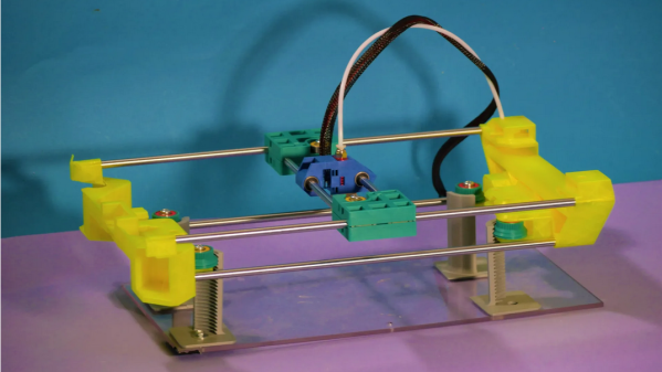
Not really, but the Infini-Z 3D printer certainly has some interesting features that us further down the road to self-replication. As the name implies, [SunShine]’s new printer is an infinite Z-axis design that essentially extrudes its own legs, progressively jacking its X- and Y-axis gantry upward. Each leg is a quarter of an internally threaded tube that engages with pinion gears to raise and lower the gantry. When it comes time to grow the legs, the print head moves into each corner of the gantry and extrudes a new section onto the top of each existing leg. The threaded leg is ready to use in minutes to raise the gantry to the next print level.

The ultimate goal of this design is to create a printer that can increase its print volume enough to print a copy of itself. At this moment it obviously can’t print a practical printer — metal parts like bearings and shafts are still needed, not to mention things like stepper motors and electronics. But [SunShine] seems to think he’ll be able to solve those problems now that the basic print volume problem has been addressed. Indeed, we’ve seen complex print-in-place designs, assembly-free compliant mechanisms, and even 3D-printed metal parts from [SunShine] before, so he seems well-positioned to move this project forward. We’re eager to see where this goes. Continue reading “Infinite Z-Axis Printer Aims To Print Itself Someday”

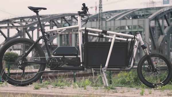
A silver and black bike sits in front of a dark grey bridge. It is on a hard surface next to green grass. The bike has a large basket area in front of the steering tube that then connects to the front wheel which is at the other end of the basket from the handlebars. It is best described as a long john bike, but is a more modern take on it than the wooden box Dutch bike.

Building A Cargo Bike Dream

Cargo bikes can haul an impressive amount of stuff and serve as a car replacement for many folks around the world. While there are more models every year from bike manufacturers, the siren song of a custom build has led [Phil Vandelay] to build his own dream cargo bike.

The latest in a number of experiments in hand-built cargo bike frames, this electrified front-loader is an impressive machine. With a dual suspension and frame-integrated cargo area, this bike can haul in style and comfort. It uses a cable steering system to circumvent the boat-like handling of steering arm long john bikes and includes a number of nice touches like (mostly) internal cable routing.

The video below the break mostly covers welding the frame with [Vandelay]’s drool-worthy frame jig, so be sure to watch Part 2 of the video for how he outfits the bike including the internal cable routing and turning some parts for the cable steering system on the lathe. If you get an urge to build your own cargo bike after following along, he offers plans of this and some of his other cargo bike designs. [Vandelay] says this particular bike is not for the beginner, unlike his previous version built with square tubing.

Looking for more DIY cargo bikes? Checkout this Frankenbike, another front loader, or this Russian trike.

Continue reading “Building A Cargo Bike Dream”

Hackaday Links Column Banner

Hackaday Links: July 30, 2023

A couple of weeks ago, we noted with interest that the space shuttle Endeavour (OV85) would be set up as a full-stack launch configuration display, complete with external fuel tank and solid rocket boosters. We predicted that this would result in some interesting engineering, not least of which will be making the entire 20-story stack safe from seismic activity. Looks like we were right on all counts, with this story about the foundation upon which the display will stand, which has been under construction for quite a while now. The base has six seismic isolators that support the 2.4-m thick slab of reinforced concrete that will serve as a perch for the full stack. The 1,800-ton slab will be able to move a meter or so from its resting position during earthquakes. Or perhaps more accurately, the foundation will allow Los Angeles to move as much as it wants while Endeavour rides it out.

If like us you’re worried that seismic loads are vastly different than the loads the spacecraft was actually designed for, relax — it turns out that the flight loads are far in excess of predicted loads from seismic stress. The plan is to build the booster stacks first — the aft skirts, which will support the entire stack, were just bolted in place — then lift the external tank in place between the boosters, and finally hoist the actual orbiter into place. After the stack is complete, the rest of the building will be built around it. We’re really looking forward to seeing some video on this project.

Continue reading “Hackaday Links: July 30, 2023”

Vehicle-to-Grid Made Easy

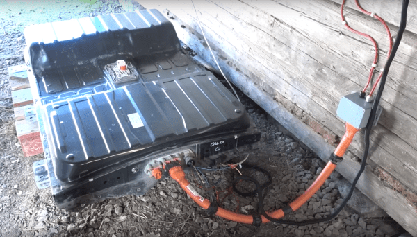
As electric cars continue to see increased adoption, one associated technology that was touted long ago that still hasn’t seen widespread adoption is vehicle-to-grid or vehicle-to-home. Since most cars are parked most of the time, this would allow the cars to perform load-levelling for the grid or even act as emergency generators on an individual basis when needed. While this hasn’t panned out for a variety of reasons, it is still possible to use an EV battery for use off-grid or as part of a grid tie solar system, and now you can do it without needing to disassemble the battery packs at all.

Normally when attempting to use a scrapped EV battery for another use, the cells would be removed from the OEM pack and reorganized to a specific voltage. This build, however, eliminates the need to modify the packs at all. A LilyGO ESP32 is used to convert the CAN bus messages from the battery pack to the Modbus communications protocol used by the inverters, in this case a Fronius Gen24, so the inverter and battery can coordinate energy delivery from one to the other automatically. With the hard part out of the way, the only other requirements are to connect a high voltage DC cable from the battery pack to the inverter.

[Dala], the creator of this project, has taken other steps to ensure safety as well that we’d recommend anyone attempting to recreate this build pays close attention to, as these battery packs contain an extremely large amount of energy. The system itself supports battery packs from Nissan Leafs as well as the Tesla Model 3, which can usually be found for comparably low prices. Building battery energy storage systems to make up for the lack of commercially-available vehicle-to-home systems isn’t the only use for an old EV battery, though. For example, it’s possible to use Leaf batteries to triple the range of other EVs like [Muxsan] did with this Nissan van.

Continue reading “Vehicle-to-Grid Made Easy”