The range of characters that can be represented by Unicode is truly bewildering. If there’s a symbol that was ever used to represent a sound or a concept anywhere in the world, chances are pretty good that you can find it somewhere in Unicode. But can many of us recall the proper keyboard calisthenics needed to call forth a particular character at will? Probably not, which is where this Unicode binary input terminal may offer some relief.
“Surely they can’t be suggesting that entering Unicode characters as a sequence of bytes using toggle switches is somehow easier than looking up the numpad shortcut?” we hear you cry. No, but we suspect that’s hardly [Stephen Holdaway]’s intention with this build. Rather, it seems geared specifically at making the process of keying in Unicode harder, but cooler; after all, it was originally his intention to enter this in last year’s Odd Inputs and Peculiar Peripherals contest. [Stephen] didn’t feel it was quite ready at the time, but now we’ve got a chance to give this project a once-over.
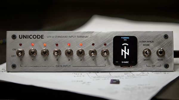
The idea is simple: a bank of eight toggle switches (with LEDs, of course) is used to compose the desired UTF-8 character, which is made up of one to four bytes. Each byte is added to a buffer with a separate “shift/clear” momentary toggle, and eventually sent out over USB with a flick of the “send” toggle. [Stephen] thoughtfully included a tiny LCD screen to keep track of the character being composed, so you know what you’re sending down the line. Behind the handsome brushed aluminum panel, a Pi Pico runs the show, drawing glyphs from an SD card containing 200 MB of True Type Font files.
At the end of the day, it’s tempting to look at this as an attractive but essentially useless project. We beg to differ, though — there’s a lot to learn about Unicode, and [Stephen] certainly knocked that off his bucket list with this build. There’s also something wonderfully tactile about this interface, and we’d imagine that composing each codepoint is pretty illustrative of how UTF-8 is organized. Sounds like an all-around win to us.