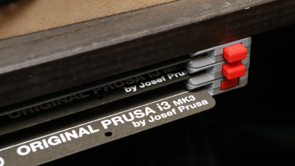
For best results, a build sheet for a 3D printer’s print bed should be handled and stored by the edges only. To help make that easier, [Whity] created the Expandable Steel Sheet Holder system that can store sheets efficiently without touching their main surfaces, and has a clever mechanism for ejecting them at the push of a button.
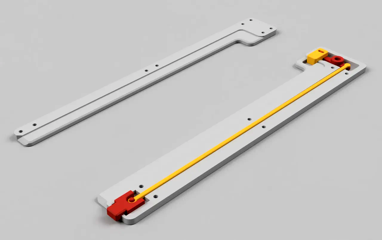
The design is 3D printable and made to be screwed to the bottom of a shelf, which is great for space saving. It can also be extended to accommodate as many sheets as one wishes, and there’s a clever method for doing that.
Once the first unit is fastened to a shelf, adding additional units later is as simple as screwing them to the previous one with a few M3 bolts, thanks to captive nuts in the previously-mounted unit. It’s a thoughtful feature that makes it easy to expand after the fact. Since build sheets come in a variety of different textures and surfaces for different purposes, one’s collection does tends to grow.
Interested, but want it to fit some other manufacturer’s sheets? The design looks easy to modify, but before you do that, check out the many remixes and you’re likely to find what you’re looking for. After all, flexible magnetic build sheets are useful in both resin and filament-based 3D printing.