Symmetry is everywhere in our natural world. Just take a look at your hands, a butterfly, or a sunflower. It’s easy to pass off the idea of symmetry and symmetric structures as a simple quirk of existence, and to pay it little mind. If this is your view, I can assure you it will no longer be by the end of this series. If we force ourselves to look beyond the grade school applications of symmetry, we find a world rich in connections via many different types of symmetric identities. One of the most interesting is Gauge Symmetry, which lies at the heart of Quantum Electrodynamics, or QED (we’ll get into this a bit later in the series). Several branches of higher level mathematics study symmetry in detail, allowing a host of sciences, from physics to chemistry, to view difficult problems and theories from a different perspective.
The subject matter of the ideas explored in symmetry is complicated, and not well known outside of academia and the theoretical sciences. It is the goal of this series of articles to simplify some of the concepts that underpin the study of symmetry, so that the average hacker can gain a basic (and I mean basic) understanding of this fascinating body of knowledge, and put it to use in future projects. We’ll start things off by taking a look at a machine that has crossed the Hackaday server many times – those nifty Rubik’s Cube solvers. Just how do those things work anyway?
Continue reading “Symmetry For Beginners – The Rubik’s Cube”
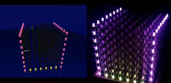
 We’re not just talking about driving the LEDs themselves at a low level, but