The Multiple Arcade Machine Emulator, now known simply as MAME, started off as a project to emulate various arcade games. The project is still adding new games to its library, but the framework around MAME makes it capable of emulating pretty much any older computer. The computer doesn’t even need to be a gaming-specific machine as the latest batch of retro hardware they’ve added support for is a number of calculators from the 90s and early 00s including a few classics from Texas Instruments.
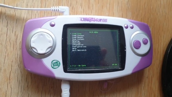
Since no one is likely to build an arcade cabinet version of a TI-89, all of these retro calculators are instead emulated entirely within a browser. This includes working buttons and functions on an overlay of each of these calculators but also pixel-accurate screen outputs for each of these. The graphing calculators have more of what we would consider a standard computer screen, but even the unique LCDs of some of the more esoteric calculators are accurately replicated as well thanks to the MAME artwork system.
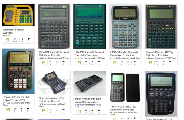
There are a number of calculators implemented under this project with a full list found at this page, and the MAME team has plans to implement more in the future. If you’re looking for something fun to do on a more modern calculator, though, take a look at this build which implements ray tracing on a TI-84 Plus CE.
Thanks to [J. Peterson] for the tip!

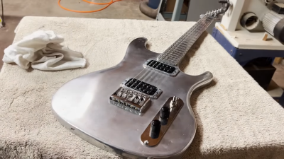 Both the body and neck of the electric guitar are made out of aluminium. It’s an impressive effort, as manufacturing a usable neck requires care to end up with something actually playable when you’re done with it.