Your Next Oscilloscope Might Be Optical

What’s better than a 100MHz scope? How about an optical one? Researchers at the University of Central Florida think that’s just the ticket, and they’ve built an oscilloscope that can measure the electric field of light. You can find the full paper online.

Reading the electrical field of light is difficult with traditional tools because of the very high frequency involved. According to [Michael Chini], who worked on the new instrument, the oscilloscope can be as much as 10,000 times faster as a conventional one.

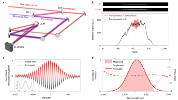
The measurement of a few cycles of light requires some special techniques as you might expect. According to the paper:

[A]n intense fundamental pulse with a central wavelength of 3.4 µm creates charge packets in the pixels of a silicon-based image sensor via multiphoton excitation, leading to detectable photocurrents. The probability of excitation is perturbed by the field of a weak perturbation pulse, leading to a modulation in the excitation probability and therefore in the magnitude of the detected photocurrent. We have previously shown that, for collinear fundamental and perturbation pulses, the dependence of the modulation in the excitation probability on the time delay between the two pulses encodes the time-varying electric-field waveform of the laser pulse. Here, by using a crossed-beam geometry with cylindrical focusing, we map the time delay onto a transverse spatial coordinate of the image sensor chip to achieve single-shot detection.

Did you get that? In other words, instead of measuring the light pulse directly, they measure the change it makes on another known signal. We think…

Unless you’re moving high-speed data across fiber optic, we aren’t sure you really need this. However, the concept is intriguing and not previously unheard of. For example, we’ve seen capacitance meters that measure the change in frequency caused by adding an unknown capacitor into an existing oscillator.

If you want something more conventional, maybe look at some popular scopemeters. Of course, something this high speed might be able to apply time-domain reflectometry to fiber optics. Maybe.

Tiny Switch Ornament Plays GIFs With An ESP32

It constantly amazes us what we hackers can build these days, (electronics shortages aside) we have access to an incredible array of parts, with specifications that only a few years ago would be bank-breaking and longer ago just fantasy. It’s nice to see people building one-offs just for fun, in spite of the current difficulties getting parts to actually be delivered. For example, check out this miniaturized Nintendo Switch created by [scottbez1] that plays animated GIFs from an SD card on tiny 1.14″ LCD display.

Obviously such a diminutive hack requires a custom PCB, which was a job for KiCAD. Armed with a 3D model of the LCD, the casing and PCB outline were drawn using Fusion 360. The PCB hosts a LilyGo ESP32 module for all the heavy lifting, with the WiFi adding some fun future capabilities not yet explored. The design is about as tight as it can get without pushing the limits of the PCB process too far, including a neat trick of sneaking passives inside the body of the SD card! That’s another space-saving idea we’ll be banking.

All-in-all a neat little hack, showing some good modelling and construction techniques and a good looking end result. Code for your reference may be found on the project GitHub, but as of writing the hardware design is not available.

Whilst this project shrinks the Switch, here’s one that goes the other way and super-sizes it, and if you have a switch lite but crave a little modern charging magic, then look no further than this Qi wireless charging hack.

Continue reading “Tiny Switch Ornament Plays GIFs With An ESP32”

A briefcase sized electronic machine with many indicator lamps and switches

Restoring A Vintage IBM I/O Tester

By now, [CuriousMarc] and his team of volunteers are well versed in 1960s hardware restoration. So when a vintage IBM I/O Tester came into their possession, a full machine makeover was all but inevitable.

The I/O Tester dates from around 1965, which roughly coincides with the introduction of IBM’s lauded System/360 computer mainframe. In addition to the computer itself, business customers could order a variety of peripherals with their computing system. These included storage devices, printers, additional operator consoles, and so on. Since these peripherals shared the same I/O design, a portable hardware testing rig was a sensible design choice. One portable low-voltage tester could be paired with any number of IBM peripherals, doing away with the need to have unique debugging panels on every piece of computing hardware.

Fast forward to the present day, and the IBM I/O Tester looks positively antique with its blinkenlight lamp panel and switches. To use the tester, simply connect up one (or both) of its chunky 104-pin connectors to your IBM peripheral of choice, insert the accompanying paper overlay, and voilà. Operators could then observe the status of the many lamps to evaluate the inner digital workings of the connected peripheral. Depending on the connected hardware, the tester could reveal the contents of data registers, printing status, disk and tape transfer status, and probably much more. The purpose of the tester’s ninety indicator lights is completely dependent on the attached peripheral, and the paired paper overlays are essential to comprehend their meaning.

After [Ken Shirriff] deciphered the documentation, it wasn’t long before the tester could be powered up using 24 VAC (normally supplied by the equipment being tested). Several burned out lamps were noted for replacement. The lamp assemblies required minor surgery due to a dubious design choice, and at least one of the toggle switches needed a new guide and a heavy dose of contact cleaner before it came back to life.

For the moment, [CuriousMarc] is using the blinkenlights panel as a surprisingly striking retro clock. With a literal truckload of vintage IBM hardware sitting in his storage, it’ll be exciting to see whether this restored tester will be pulled back into operational service someday. Readers should also check out our coverage of his previous major project, restoring an Apollo Guidance Computer.

Continue reading “Restoring A Vintage IBM I/O Tester”

Kamehameha!! PCB Badge

PCB Art has surely captivated us over the past few years and we’re ever intrigued with the intricate detail the community puts into their work. We’re no strangers to [Arnov]’s work and he has impressed, yet again, with his Kamehameha PCB badge.

Unfortunately, no 555 timer was used in the making of this project, but don’t let that turn you away. Instead, we have an ATtiny84 microcontroller for implementing the logic to control the LEDs, a MOSFET-based driver for driving current through the LEDs, and, of course, the LEDs to give the “turtle destruction wave” its devastating glow. Pay really close attention to the detail [Arnov] put into the silkscreen as you can see that’s a pretty crucial part of this build.

Aside from marveling at [Arnov]’s work, fans of the OrCAD PCB designing software will learn how to import an image file into their project as [Arnov] walks through that step in his tutorial. He even has some pretty good reflow soldering tips if you’re looking to try your hand at SMD soldering.

Another cool build [Arnov]. Keep it up!

Continue reading “Kamehameha!! PCB Badge”

When Does Car Hacking Become “Tampering”? The British Government Seeks Guidance

When a government decides to take a look at your particular field of experimentation, it’s never necessarily a cause for rejoicing, as British motor vehicle enthusiasts are finding out through a UK Government consultation. Titled “Future of transport regulatory review: modernising vehicle standards“, the document explains that it is part of the process of re-adopting under UK law areas which have previously been governed by the European Union. Of particular interest is the section “Tackling tampering”, which promises a new set of offences for “tampering with a system, part or component of a vehicle intended or adapted to be used on a road“.

They go into detail as to the nature of the offences, which seem to relate to the production of devices designed to negate the safety or environmental features of the car. They’re at pains to say that they have no wish to target the legitimate car modification world, for example in motorsport or restoration, but it’s easy to see how a car hacker might inadvertently fall foul of any new rules. It’s worried the enthusiasts enough that a petition has been launched on the UK parliamentary petition site, making the point that the existing yearly MOT roadworthiness test should fulfill the function of taking any illegal vehicles off the road.

We’re always wary when governments wander into our purview, and given where this is being written it’s fair to say that British governments have had their fair share of ill-considered laws in their time. But before we call doom upon the future of car hacking for Brits, it’s worth remarking that they don’t always make a mess in this arena. The rules for the Individual Vehicle Approval test for putting a home-built car on the road are far from a bureaucratic nightmare for example, instead being a relatively sensible primer in building a safe motor vehicle.

So we’d suggest not to panic just yet, but perhaps any British readers might like to respond appropriately to the consultation and the petition in the interests of nudging them in the right direction.

Thanks [Adam Quantrill] for the tip.

OpenDog Version 3 Is Ready To Go Walkies

We’ve been following [James Bruton]’s open dog project for a little while now, and with his considerable pace of work – pandemic or no pandemic – development has been incredibly rapid. The latest milestone is the public release of version 3 (Video, embedded below.) This upgrade to the system adds 3D printed cycloidal gearboxes, removing the previous belt drives. [James] had immense fun tuning the motor controller parameters for these and admits they’re not completely dialed in yet. He notes that the wider gearbox body means that the robots geometry needed to change a little, and the previous belt-drive version may have a bit of an edge, but he’s confident he can make it work (and given his incredible previous robotics builds, we totally believe he’ll nail it!)

Silicone overmolding around a 3D printed former, using a 3D printed mould

Older versions struggled with slippery plastic feet; the advantage of a predictably smooth contact shape of a rounded foot is somewhat offset by the limited contact patch size, and that means not so much grip on some surfaces. [James] solution was obvious enough – just learn how to make 3D printed silicone moulds and cast a nice rubber foot around a plastic former, and problem solved! Unfortunately he neglected to add some recesses for a lever to get in between the mould halves, so it was a bit of a struggle to separate after curing. A beginner’s mistake that won’t be repeated, we’re sure.

Full source for openDogV3 is now available on the GitHub page. Here’s the playlist for the whole project, as well as direct links for the cycloidal drive development (part1, part2, part3.) But before you all go diving in to start 3D printing your own pooch, [James] tells us that the total cost would be around $2000 all in, with the bulk of that being the motors and ODrive units, so this one for the serious builder only!

We’ve covered robot dogs a fair bit, a particularly nice example is The Dizzy Wolf, and if you’re wondering just why on earth you’d want a robot dog, then Ask Hackaday has you covered as well.

Continue reading “OpenDog Version 3 Is Ready To Go Walkies”

An orange 3D printed four digit clock with rotating segments

Be Mesmerized By The Latest Time Twister

[Hans Andersson] has been creating marvelous twisting timepieces for over a decade, and we’re pleased to be able to share his latest mechanical clock contraption with our readers, the Time Twister 5.

In contrast to his previous LEGO-based clocks, version five of the Time Twister uses 3D printed segments, undoubtedly providing greater flexibility in terms of aesthetics and function. Each digit is a mechanical display, five layers vertical and three segments horizontal, with a total of three unique faces. Each layer of each display can be individually rotated by a servo, and this arrangement allows for displaying any number between zero and nine. The whole show is controlled by an Arduino MEGA and a DS3231 real-time clock.

Watching these upended prisms rotate into legible fifteen-segment digits is enjoyable enough already, but the mechanical sound created by this timepiece in motion is arguably even more satisfying. Check out the video below to see (and hear) for yourself. If you want to build one yourself, all the details are here.

We last covered [Hans Andersson] and his very first Time Twister clock way back in November 2011. Since then we’ve come across many impressive mechanical clocks, like this seven-segment work of art. We’re constantly impressed by the outstanding craftsmanship of these mechanical clocks, and it’s inspiring to see one of our OG horologists back in the saddle once more.

Continue reading “Be Mesmerized By The Latest Time Twister”