For British teenagers in the 1980s, the delights of 8-bit computers such as the Sinclair Spectrum, Commodore 64, or BBC Micro were firmly restricted to the offline arena. We would read about the BBS scene on the other side of the Atlantic, but without cheap local calls and with a modem costing a small fortune, the chances of us ever experiencing one was zero. When we took the British school rite of passage of a trip to France though, we were astounded to see that every French person was not merely online, but that they were doing so with a neat little all-in-one terminal. We’d just been introduced to the French Minitel system, and in that minute shared a glimpse of the future.
Un Réseau Trés Français
In the 1970s and 1980s, so-called videotext systems, terminal-based phoneline access to information services on central computers, were seen as an obvious next step for telephone network operators with an interest in profitable new products. In most countries this resulted in services such as the UK’s Prestel, a subscription service relying on costly hardware, but France Télécom instead pursued the bold path of making the terminals free to subscribers with free access to phone listings and yellow pages, but a business model based on pay-to-use premium services.
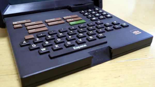
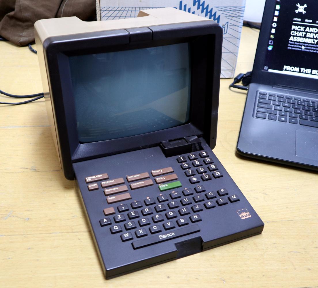
Thus, through the 1980s all French households had a Minitel terminal beside the phone, and the service became a runaway success. Ever since seeing Minitel terminals as a tourist I’d been fascinated by the service, so here in the 2020s when a friend was visiting their family in France I asked whether he could pick up an old Minitel terminal for me. Thus I found myself parting with around $25 and being rewarded with a slightly battered Minitel cardboard box containing one of the familiar brown Alcatel terminals. I certainly wasn’t expecting one in its original packaging. Continue reading “Teardown: Alcatel Telic 1 Minitel Terminal”