The use of aluminium in wiring is unlikely to bring a smile to the face of anyone who has had to deal with it in a 1960s, or early 1970s-era house. The causes behind the fires and other accidents were myriad, including failure to deal with the higher thermal expansion of aluminium, the electrically insulating nature of aluminium oxide, and the general brittleness of aluminium when twisted.
Yet while copper is superior to aluminium in terms of electrical conductivity and ease of installation, copper prices have skyrocketed since the 1970s, and are on the verge of taking off to the moon. A big part of the reason is the increased use of copper in everything from electronics and electrical motors to generators, driven by large-scale deployment of wind turbines and electrical vehicles.
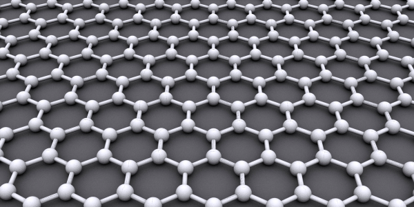
As the world moves to massively expand the use of electrical cars and installation of wind turbines, copper demand is predicted to outstrip current copper supply. With aluminium likely to make a big return as a result, it’s worth taking a look at modern-day aluminium-based wiring, including copper-clad aluminium and the use of carbon-based replacements. Continue reading “The Coming Copper Shortage: Aluminium Or Carbon Nanotubes To The Rescue?”