We’re not here to talk about another clock. Okay, we are, but the focus isn’t about whether or not it can tell time, it’s about taking a simple idea to an elegant conclusion. In all those ways, [Marcin Saj] produced a beautiful project. Most of the nixie clocks we see are base-ten, but this uses base-two for lots of warm glow from more than a dozen replaceable units.
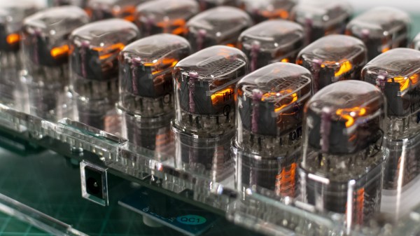
There are three rows for hours, minutes, and seconds. The top and bottom rows are labeled with an “H” and “S” respectively displayed on IN-15B tubes, while the middle row shows an “M” from an IN-15A tube. The pluses and minuses light up on IN-12 models so you’ll need eighteen of them for the full light show, but you could skimp and use sixteen in twelve-hour mode since you don’t need to count to twenty-four. We won’t explain how to read time in binary, since you know, you’re here and all. The laser-cut acrylic is gorgeous with clear plastic next to those shiny nixies, but you have to recreate the files or buy the cut parts as we couldn’t find vector files amongst the code and schematics.
Silly rabbit, nixies aren’t just for clocks. You can roll your own, but they’re not child’s play.