Around these parts, we see plenty of plotter builds. They’re a great way to learn about CNC machines and you get to have fun making pictures along the way. [Ben Lucy] was undertaking just such a build of his own, but wanted to do something standalone that served a purpose. The result is the impressive Portable Portrait Painter.
What sets [Ben]’s project apart is how complete it is. Unlike other plotters that simply follow G-code instructions or process external images, the Portable Portrait Painter is a completely standalone machine. Fitted out with an OV7670 camera, hooked up to an Arduino, it’s capable of taking its own photos and then drawing them out as well.
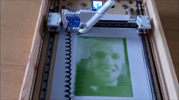
Through some clever code from [Indrek Luuk], the Arduino Mega2560 is able to display a 20fps video preview on a color LCD screen. When the user presses a button, the current frame is captured and sent to the pen plotter. The plotting algorithm is particularly impressive, with images first processed with histogram compensation to maximise contrast. The pen is then drawn across the page line by line, and pressed into the page by varying amounts depending on the color value of each pixel. The darker the pixel, the thicker the stroke made by the pen. This more analog approach produces a much more detailed image than more basic plotters which either leave a mark or don’t.
The portraits produced by the plotter are impressive, and we like the edge-of-page artifacts, which add a little style to the final results. The Portrait Painter would make a great conversation piece at any Maker Faire or hackerspace night.
It’s a project that reminds us of some of the painting robots we’ve seen over the years. Video after the break.