Back in the early 1980s, there was a certain fad in making your computer produce something resembling human speech. There were several hardware solutions to this, adding voices to everything from automated telephone systems to video game consoles, all the way to Steve Jobs using the gimmick to introduce Macintosh to the world in 1984. In 1982, a software-based version of this synthesis was released for the Atari 8-bit line of computers, and ever since them [rossumur] has wondered whether or not it could run on the very constrained 2600.
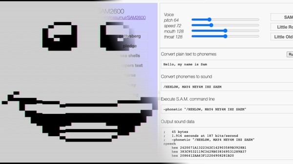
Fast-forward 38 years and he found out that the answer was that yes, it was indeed possible to port a semblance of the original 1982 Software Automatic Mouth (or SAM) to run entirely on the Atari 2600, without any additional hardware. To be able to fit such a seemingly complicated piece of software into the paltry 128 bytes (yes, bytes) of RAM, [rossumur] actually uses an authoring tool in order to pre-calculate the allophones, and store only those in the ROM. This way, the 2600 alone can’t convert text to phonemes, but there’s enough space left for the allophones, which are converted into sound, that about two minutes of speech can fit into one cartridge. As for why he went through the trouble, we quote the author himself: “Because creating digital swears with 1982 speech synthesis technology on a 1977 game console is exactly what we need right now.”
For this project, [rossumur] has written an incredibly interesting article on speech synthesis in order to explain the SAM engine used here. And this isn’t his first time on the website either, always cramming software where it shouldn’t fit, such as a “Netflix”-like streaming service, or 8-bit console emulators, both on nothing but an ESP32 microcontroller. Check this one out in action after the break.
Continue reading “38 Years Later, The Atari 2600 Learns To Speak” →