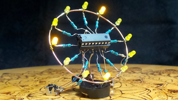
Here at Hackaday, we love a good clock project. And if it’s an artistically executed freeform sculpture, even better. But tell us that it’s also a new spin on a classic project from two decades ago, and we’re over the moon for it. Case in point: [Paul Gallagher’s] beautiful recreation of an LED clock riffing on one originally made as a weekend project in early 2000.
Wait, wait. Hold up.
*Ted unclips the microphone from his lapel and stands up from his chair*
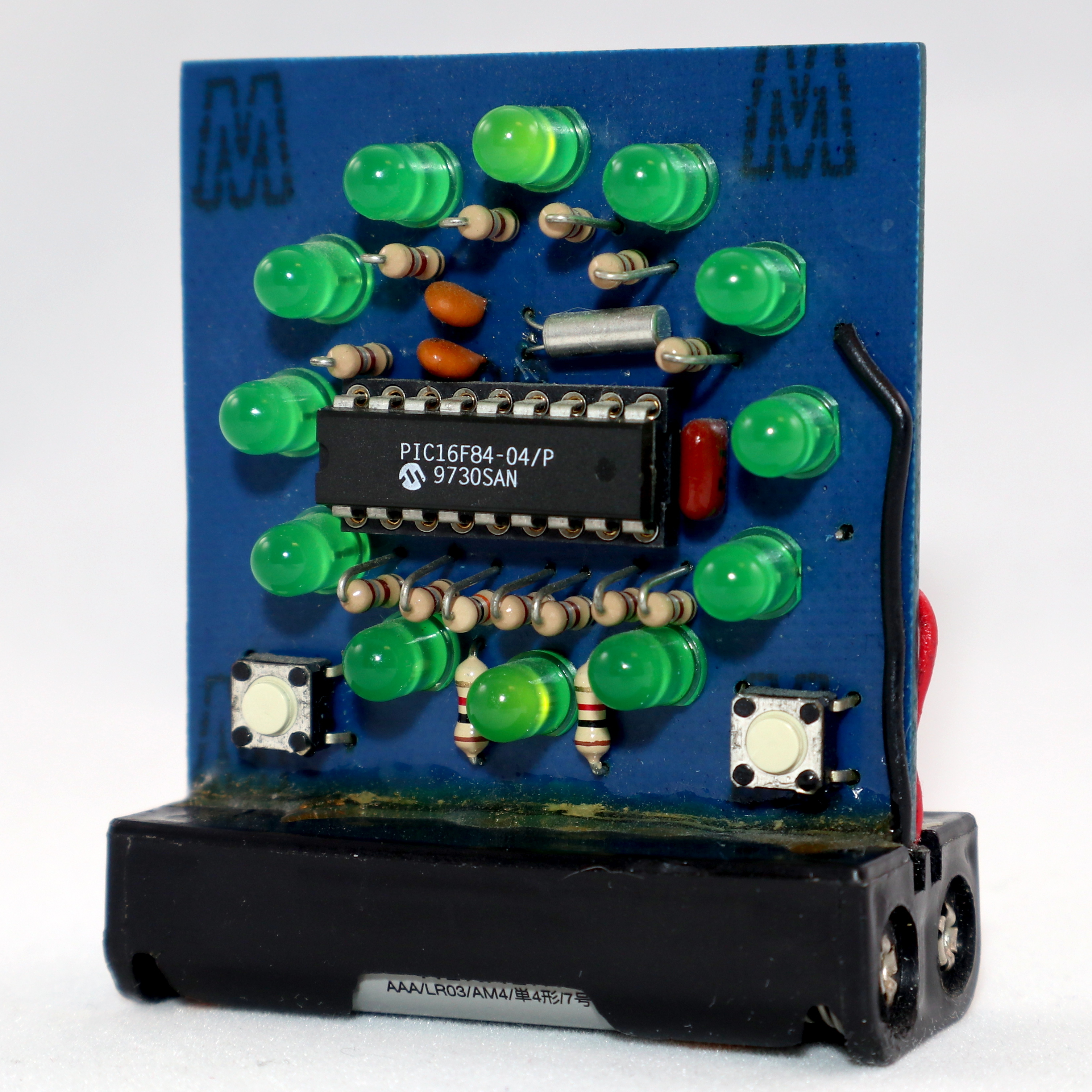
OK, dear reader, if you’ll allow me, we’re going to do this one a little differently. Normally I’m supposed to write in the voice of Hackaday, but this project has personal meaning for me, so I’d like to break the rules a bit. You see, the original clock project was mine — one I did over a weekend a long time ago, as evidenced by the “2/13/2000” date on the PCB — and I was quite honored that [Paul] would choose my project as inspiration.
When, on the 20th anniversary of creating this clock, I posted a Twitter thread to commemorate the event, [Paul] picked up the ball and ran with it. You can see the original Twitter thread here. Pictures of the home-etched single-sided board were all he needed to reverse-engineer the relatively simple design, and then re-create it with style.
The design uses a PIC16F84 microcontroller. This was one of the first microcontrollers to really become popular with hobbyists, the key features being the serial programming algorithm which allowed easy homebrew programmers, and the FLASH memory. If I recall correctly, my original programmer ran off a PC’s parallel port. I probably have it in a box somewhere. Each of the 12 LEDs is driven through a separate resistor from individual GPIO lines, while a 32.768 kHz crystal serves as the timebase. Finally, two buttons allow you to set the hours and minutes.
How do you represent three separate hands on such a display? In this case, each hand blinks at a different rate. The hour LED is solid, and the second LED blinks faster than the minute one. You can check it out in [Paul’s] video after the break, and admire the beautiful simplicity of his layout.
Since he was able to re-create the circuit exactly, [Paul] was able to drop-in the original assembly code that runs the clock. True-to-form, Microchip still manufactures the PIC16F84, and their latest tools have no problem with such legacy code — it just works.
Continue reading “Beautiful Free-Form LED Clock Recreates 20-Year-Old Weekend Project”