Why The 555 Is Not A Timer, But Can Be One

Although commonly referred to as a ‘timer IC’, the venerable NE555 and derivatives are in fact not timer ICs. This perhaps controversial statement is the open door that gets kicked in by [PKAE Electronics] over at YouTube, as he explains with excellent diagrams and simulations how exactly these ICs work, and what it takes to make it actually do timer things. For anyone who has ever used one of these chips there is probably nothing too mind-blowing, but it’s an infinitely better way to wrap your way around an NE555 and kin than a datasheet.

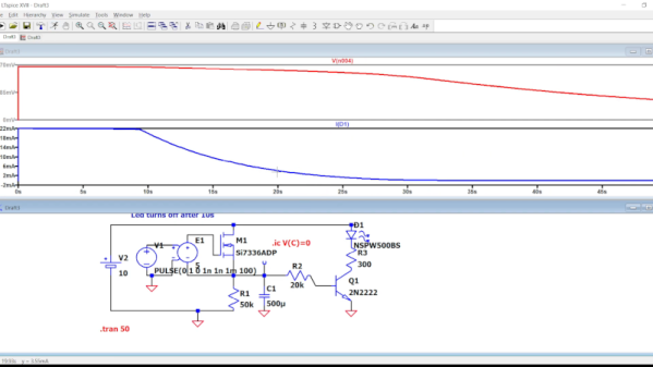
At its core, the 555 contains three 5 kOhm resistors as a voltage divider, which has been incorrectly postulated to be the source of the chip’s name. This voltage divider controls two comparators, which in turn control an SR flipflop. These comparators are used for the voltage trigger and threshold inputs, which in turn toggle the flipflop, respectively setting and resetting it. This by itself just means that the 555 can be used as a threshold detector, with settable control voltage. How a 555 becomes a timer is when the discharge, trigger and threshold pins are combined with external resistors and a capacitor, which creates a smooth square wave on the 555’s output pin.

There are many ways to make basic components into an oscillator of some type, but the 555 is a great choice when you want something more refined that doesn’t involve using an entire MCU. That said, there’s far more that the 555 can be used for, as [PKAE] alludes to, and we hope that he makes more excellent videos on these applications.

Continue reading “Why The 555 Is Not A Timer, But Can Be One”

Bringing The 555 Mini-Notebook To Video

Like many of us [AnotherMaker] is a fan of the classic Forrest Mims electronics books, specifically, the Engineer’s Mini-Notebook series. They were great sources of inspiration, but at the time, he couldn’t afford to actually build most of the circuits described. Now as an adult, he decided to go through the 555 Timer IC Circuits Mini-Notebook, full of example circuits and explanations, all in Mims’ trademark handwritten style, and build all the circuits for real. And so, a series of YouTube videos are currently being released going over every circuit, how it works, and looking at waveforms on an oscilloscope!

So, PCBs were designed, each containing four of the circuits from the book. With the Mims circuit diagram on one side of the screen and the PCB on the other, [AnotherMaker] goes into a good amount of detail explaining how each circuit works, referring to the schematic and oscilloscope as needed. Each part in the series focuses on the next circuits in order, and eventually the whole series will cover every single circuit in the book.

It’s a great series of videos for anyone learning electronics, especially those who would like to learn about one of the most produced integrated circuits of all time! It’s also an excellent way to bring a fresh perspective to this classic book, while simultaneously bringing the content to a wider audience via online video.

Continue reading “Bringing The 555 Mini-Notebook To Video”

2024 Business Card Challenge: T-800’s 555 Brain

In Terminator 2: Judgment Day it’s revealed that Skynet becomes self-aware in August of 1997, and promptly launches a nuclear attack against Russia to draw humanity into a war which ultimately leaves the door open for the robots to take over. But as you might have noticed, we’re not currently engaged in a rebellion against advanced combat robots.

The later movies had to do some fiddling with the timeline to explain this discrepancy, but looking at this 2024 Business Card Challenge entry from [M. Bindhammer] we think there’s another explanation for the Judgement Day holdup — so long as the terminators are rocking 555 timers in their chrome skulls, we should be safe.

While the classic timer chip might not be any good for plotting world domination, it sure does make for a great way to illuminate this slick piece of PCB art when it’s plugged into a USB port. Exposed copper and red paint are used to recreate the T-800’s “Brain Chip” as it appeared in Terminator 2, so even when the board isn’t powered up, it looks fantastic on display. The handful of components are around the back side, which is a natural place to put some info about the designer. Remember, this is technically supposed to be a business card, after all.

Continue reading “2024 Business Card Challenge: T-800’s 555 Brain”

Hackaday Podcast Episode 267: Metal Casting, Plasma Cutting, And A Spicy 555

What were some of the best posts on Hackaday last week? Elliot Williams and Al Williams decided there were too many to choose from, but they did take a sampling of the ones that caught their attention. This week’s picks were an eclectic mix of everything from metal casting and plasma cutters to radio astronomy and space telescope budgets. In between? Some basic circuit design, 3D printing, games, dogs, and software tools. Sound confusing? It won’t be, after you listen to this week’s podcast.

Check out the links below if you want to follow along, and as always, tell us what you think about this episode in the comments!

Download an audiophile-quality oxygen-free MP3 file here.

Continue reading “Hackaday Podcast Episode 267: Metal Casting, Plasma Cutting, And A Spicy 555”

Delays And Timers In LTSpice (no 555)

If you need a precise time, you could use a microcontroller. Of course, then all your friends will say “Could have done that with a 555!” But the 555 isn’t magic — it uses a capacitor and a comparator in different configurations to work. Want to understand what’s going on inside? [Mano Arrostita] has a video about simulating delay and timer circuits in LTSpice.

The video isn’t specifically about the 555, but it does show how the basic circuits inside a timer chip work. The idea is simple: a capacitor will charge through a resistor with an exponential curve. If you prefer, you can charge with a constant current source and get a nice linear charge.

You can watch the voltage as the capacitor charges and when it reaches a certain point, you know a certain amount of time has passed. The discharge works the same way, of course.

We like examining circuits for learning with a simulator, either LTSpice or something like Falstad. It is easier than breadboarding and encourages making changes that would be more difficult on a real breadboard. If you want a refresher on LTSpice or current sources, you can kill two birds with one stone.

Continue reading “Delays And Timers In LTSpice (no 555)”

A 555-Shaped Discrete Component 555

While the “should have used a 555” meme is strong around these parts, we absolutely agree with [Kelvin Brammer]’s decision to make this 555-shaped plug-in replacement for the 555 timer chip using discrete parts, rather than just a boring old chip.

As [Kelvin] relates, this project started a while back as an attempt to both learn EDA and teach students about the inner workings of the venerable timer chip. The result was a 555-equivalent circuit on a through-hole PCB, with the components nicely laid out into the IC’s functional blocks. As a bonus, the PCB was attached to an 8-pin header which could be plugged right in as a direct replacement for the chip.

Fast forward a few years, and [Kelvin] needed to learn yet another EDA package; what better way than to repeat the 555 project? It was also a good time to step into SMD design, as well as add a little zazzle. While the updated circuit isn’t as illustrative of the internal arrangement of the 555, the visual celebration of the “triple nickel” is more than worth it. And, just like the earlier version, this one has a header so you can just plug and chug — with style.

Want to know how the 555 came to be? We’ve covered that. You can also look at some basic 555 circuits to put your 555-shaped 555 to work. We’ve even seen a vacuum tube 555 if that’s more your thing.

Back To Basics With A 555 Deep Dive

Many of us could sit down at the bench and whip up a 555 circuit from memory. It’s really not that hard, which is a bit strange considering how flexible the ubiquitous chip is, and how many ways it can be wired up. But when was the last time you sat down and really thought about what goes on inside that little fleck of silicon?

If it’s been a while, then [DiodeGoneWild]’s back-to-basics exploration of the 555 is worth a look. At first glance, this is just a quick blinkenlights build, which is completely the point of the exercise. By focusing on the simplest 555 circuits, [Diode] can show just what each pin on the chip does, using an outsized schematic that reflects exactly what’s going on with the breadboarded circuit. Most of the demos use the timer chip in free-running mode, but circuits using bistable and monostable modes sneak in at the end too.

Yes, this is basic stuff, but there’s a lot of value in looking at things like this with a fresh set of eyes. We’re impressed by [DiodeGoneWild]’s presentation; while most 555 tutorials focus on component selection and which pins to connect to what, this one takes the time to tell you why each component makes sense, and how the values affect the final result.

Curious about how the 555 came about? We’ve got the inside scoop on that.

Continue reading “Back To Basics With A 555 Deep Dive”