3D Print Your Best Friend A Wheelchair

We all know that 3D printing has been a boon for people with different life challenges. But the Ford Motor Company in Mexico wants to help dogs that need mobility assistance. They’ve designed and released P-Raptor (we presume the P is for perro), a wheelchair for pooches with rear leg issues. The web page is in Spanish, and translating it didn’t seem to work for some reason, but if you have any Spanish, you can probably work it out or cut and paste just the text into your favorite translator.

The design is modular to adapt to different size dogs and different problems. It contains an electric motor in the tires. The tires themselves are oversized to help your friend cover rugged terrain. Dogs want to look cool, too, so a grill with lighting is included.

Continue reading “3D Print Your Best Friend A Wheelchair”

Hackaday Prize 2023: Green Hacks Finalists

Time and tide wait for no hacker, even if they happen to spend their spare time working on the sort of eco-friendly projects that qualified for the Green Hacks challenge of the 2023 Hackaday Prize. This environmentally conscious round ended last month, and after plenty of carbon-neutral debate, our panel of judges have settled on their ten favorite projects.

As a reminder, the following projects will not only receive a $500 cash prize, but will move on to the Finals. They’ll then have until October to put the finishing touches on their creations in an effort to claim one of the final six awards, which includes the Grand Prize of $50,000 and a residency at the Supplyframe DesignLab. Although there can only be ten finalists for each round of the Hackaday Prize, we’d like to thank everyone who put the time and effort into submitting their Green Hacks. We’ve only got one Earth, and we’re all going to have to work together if we want to make sure it stays beautiful for future generations.

Continue reading “Hackaday Prize 2023: Green Hacks Finalists”

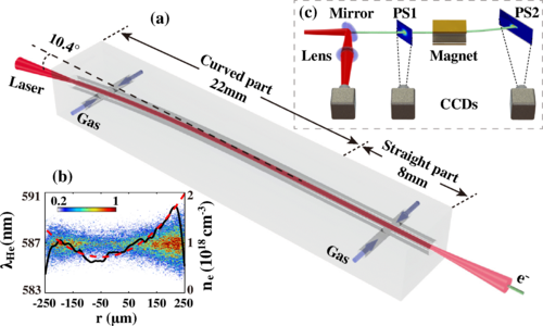
(a) Structure of the discharged capillary to produce the curved and straight plasma channel. (b) Spectrum distribution and calculated profile of the plasma density along the radial direction at the entrance of the discharged capillary. (c) Experimental setup for the measurements of laser guiding and electron acceleration. (Credit: Xinzhe Zhu et al., 2023)

Accelerating Electrons To TeV Levels Using Curved Laser Beams

There are many applications for particle accelerators, even outside research facilities, but for the longest time they have been large, cumbersome machines, not to mention very expensive to operate. Here laser wakefield accelerators (LWFAs) are a promising alternative, which uses lasers to create accelerated particles along the wake in a plasma field. One of the major struggles has been with reinjecting the thus accelerated particles into another stage of a multi-stage accelerator, which would be required to obtain energies closer to one TeV. In this area researchers have now demonstrated a way around this, by using curved channels for the laser beams (paywalled paper) which inject the laser beam into the continuous cavity. Continue reading “Accelerating Electrons To TeV Levels Using Curved Laser Beams”

A New Educational Robotics Platform

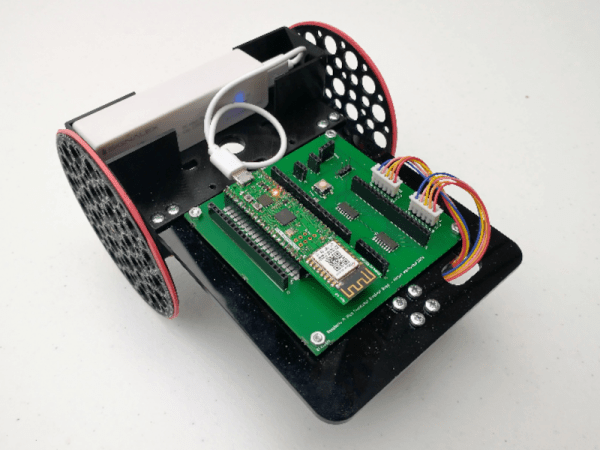
When looking for electronics projects to use in educational settings, there is no shortage of simple, lightweight, and easily-accessible systems to choose from. From robotic arms, drones, walking robots, and wheeled robots, there is a vast array of options. But as technology marches on, the robotics platforms need to keep up as well. This turtle-style wheeled robot called the Trundlebot uses the latest in affordable microcontrollers on a relatively simple, expandable platform for the most up-to-date educational experience.

The robot is built around a Raspberry Pi Pico, with two low-cost stepper motors to drive the wheeled platform. The chassis can be built out of any material that can be cut in a laser cutter, but for anyone without this sort of tool it is also fairly easy to cut the shapes out by hand. The robot’s functionality can be controlled through Python code, and it is compatible with the WizFi360-EVB-Pico which allows it to be remote controlled through a web application. The web interface allows easy programming of commands for the Trundlebot, including a drag-and-drop feature for controlling the robot.

With all of these features, wireless connectivity, and a modern microcontroller at the core, it is an excellent platform for educational robotics. From here it wouldn’t be too hard to develop line-follower robots, obstacle-avoiding robots, or maze-solving robots. Other components can easily be installed to facilitate these designs as well. If you’re looking for a different style robot, although not expressly for educational purposes this robotic arm can be produced for under $60.

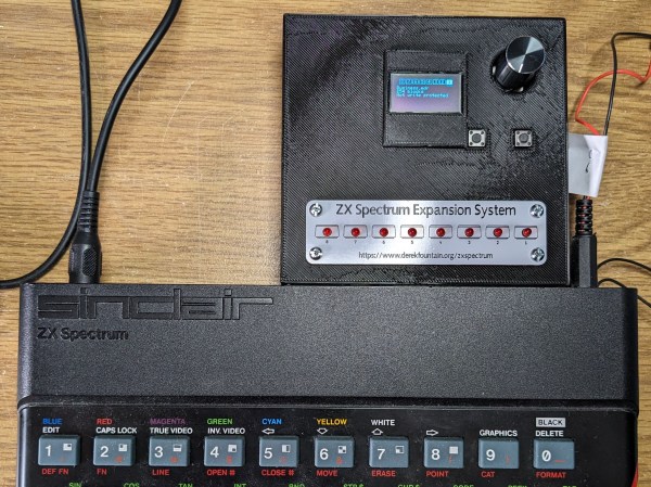
A ZX Spectrum with a Microdrive emulator plugged into its expansion port

A Modern Replacement For The ZX Spectrum’s Odd Tape Storage System

Unless you were lucky enough to be able to afford a floppy disk drive, you probably used cassette tapes to store programs and data if you used pretty much any home computer in the 1980s. ZX Spectrum users, however, had another option in the form of the Microdrive. This was a rather unusual continuous-loop mini-tape cartridge that could store around 100 kB and load it at lightning speed, all at a much lower price point than a floppy drive. The low price came at the cost of poor durability however, and after four decades it’s becoming harder and harder to find cartridges that work reliably. [Derek Fountain] therefore set out to make a modern Microdrive emulator that stores data on SD cards.

Several projects already exist to replace Microdrives, but they typically also need the ZX Interface 1, a serial/network expansion module that’s becoming equally hard to find. Hence [Derek]’s choice to make his emulator a completely standalone system that directly plugs into the Spectrum’s expansion port.

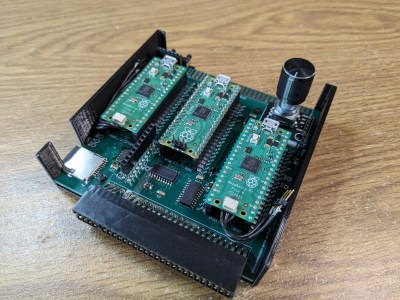
A 3D-printed box with a PCB inside holding three Raspberry Pi Picos and an SD cardThe system is housed in a 3D-printed enclosure that holds two PCBs. Three Raspberry Pi Picos run the show inside: one to hold the ZX Interface 1’s ROM image and interface with the Spectrum’s bus, another to simulate the Microdrive, and a third to run the user interface and communicate with the SD card. The user can choose between eight tape images stored in .MDR format by using two pushbuttons and a rotary encoder, with a small OLED display showing the machine’s configuration.

While you might think that three dual-core 133 MHz ARM CPUs would run circles around the Spectrum’s Z80, it actually took quite a bit of work to get everyting running properly in real time. The 3.5 MHz bus clock rate gave the second Pico precious little time to fetch the required bytes out of its flash memory. Its RAM was fast enough for that, but too small to hold all eight tape images at the same time. In the end, [Derek] settled on using a separate 8 MB SPI DRAM chip that could easily keep up the data rate, with the Pi just using its GPIO ports to shuttle the data around.

All source code and extensive documentation are available on Derek’s excellent blog post and GitHub page. Be sure to also check out [Jenny]’s detailed review and teardown if you’d like to know more about the weird and wonderful Microdrive system.

Thanks for the tip, [Andrew]! Continue reading “A Modern Replacement For The ZX Spectrum’s Odd Tape Storage System”

The Right Equipment Makes A Difference For Digital Oscilloscope Music

We all love our cheap digital oscilloscopes, and with good reason. But if there’s one place where analog scopes still shine, it’s anywhere you need X-Y mode. Digitally sampling the inputs and mapping them on the screen as discrete points just isn’t the same as steering an electron beam around a CRT, making X-Y mode work on digital scopes — at least the affordable ones — somewhat lacking.

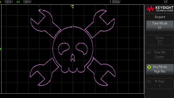
Thankfully, nobody told [Mark Hughes] that his digital scope would make a lousy X-Y display, so he just plunged ahead and figured out how to make it work anyway. The results are actually pretty good, but it took some doing. His setup begins with OsciStudio, an application built to take 3D shapes and animations and turn them into oscilloscope music. The output from that is piped to a USB sound card; [Mark] used a PreSonus Studio 26c, an adapter with DC-coupled inputs, which he found to be critical to getting good images. Also important was a USB isolator and good-quality cables, which greatly reduced jitter and made the image much more stable.

Displaying the image was as easy as connecting the left and right outputs from the sound card to the two scope inputs — [Mark] used a Keysight EDUX1052G — and setting it to X-Y mode. It took a fair amount of fiddling to get as far as he did, but we think the results speak for themselves. As for the sounds made by these images, he says it’s a bit like a hung sound card when a computer blue-screens. So, yeah — not exactly musical, but still an interesting way to have some fun with your digital scope.

PCIe For Hackers: Our M.2 Card Is Done

We’ve started designing a PCIe card last week, an adapter from M.2 E-key to E-key, that adds an extra link to the E-key slot it carries – useful for fully utilizing a few rare but fancy E-key cards. By now, the schematic is done, the component placement has been figured out, and we only need to route the differential pairs – should be simple, right? Buckle up.

Getting Diffpairs Done
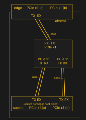
PCIe needs TX pairs connected to RX on another end, like UART – and this is non-negotiable. Connectors will use host-side naming, and vice-versa. As the diagram demonstrates, we connect the socket’s TX to chip’s RX and vice-versa; if we ever get confused, the laptop schematic is there to help us make things clear. To sum up, we only need to flip the names on the link coming to the PCIe switch, since the PCIe switch acts as a device on the card; the two links from the switch go to the E-key socket, and for that socket’s purposes, the PCIe switch acts as a host.

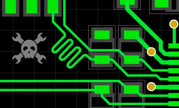
While initially routing this board, I absolutely forgot about one more important thing for PCIe – series capacitors on every data pair, on the host TX side of the link. We need three capacitor pairs here – on TX of the PCIe switch uplink, and two pairs on TX side of the switch – again, naming is host-side. I only remembered this after having finished routing all the diffpairs, and, after a bit of deliberation, I decided that this is my chance to try 0201 capacitors. For that, I took the footprints from [Christoph]‘s wonderful project, called “Effect of moon phase on tombstoning” – with such a name, these footprints have got to be good.

We’ve talked about differential pair calculations before in one of the PCIe articles, and there was a demo video too! That said, let’s repeat the calculations on this one – I’ll show how to get from “PCB fab website information” to “proper width and clearance diffpairs”, with a few fun shortcuts. Our setup is, once again, having signals on outer layers, referenced to the ground layer right below them. I, sadly, don’t yet understand how to calculate differential impedance for signal layers sandwiched between two ground planes, which is to say – if there’s any commenters willing to share this knowledge, I’d appreciate your input tremendously! For now, I don’t see that there’d be a tangible benefit to such an arrangement, anyway.

Continue reading “PCIe For Hackers: Our M.2 Card Is Done”