A Doppler Radar Module From First Principles

If you’ve ever cast your eyes towards experimenting with microwave frequencies it’s likely that one of your first ports of call was a cheaply-available Doppler radar module. These devices usually operate in the 10 GHz band, and the older ones used a pair of die-cast waveguide cavities while the newer ones use a dielectric resonator and oscillator on a PCB. If you have made your own then you are part of a very select group indeed, as is [Reed Foster] and his two friends who made a Doppler radar module their final project for MIT’s 6.013 Applications of Electromagnetics course.

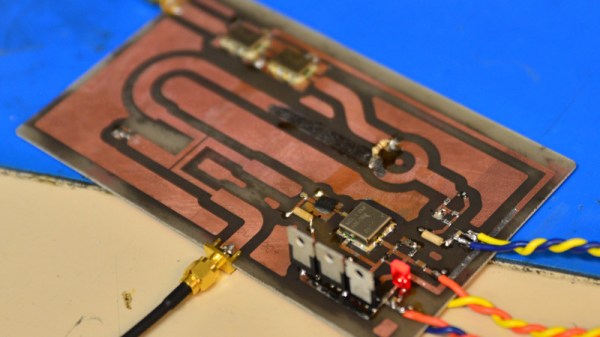
Their module runs at 2.4 GHz and makes extensive use of the notoriously dark art of PCB striplines, and their write-up offers a fascinating glimpse into the world of this type of design. We see their coupler and mixer prototypes before they combined all parts of the system into a single PCB, and we follow their minor disasters as their original aim of a frequency modulated CW radar is downgraded to a Doppler design. If you’ve never worked with this type of circuitry before than it makes for an interesting read.

We’ve shown you a variety of commercial Doppler modules over the years, of which this teardown is a representative example.

Making Autonomous Racing Drones Lean And Mean

Recently the MAVLab (Micro Air Vehicle Laboratory) at the Technical University of Delft in the Netherlands proudly proclaimed having made an autonomic drone that’s a mere 72 grams in weight. The best part? It’s designed to take part in drone races. What this means is that using a single camera and onboard processing, this little drone with a diameter of 10 centimeters has to navigate the course, while avoiding obstacles.

To achieve this goal, they took an Eachine trashcan drone, replacing its camera with an open source JeVois smart machine vision camera and the autopilot software with the Paparazzi open UAV software. Naturally, scaling a racing drone down to this size came at an obvious cost: with its low-quality sensors, relatively low-quality camera and limited processing power compared to its big brothers it has to rely strongly on algorithms that compensate for drift and other glitches while racing.

Currently the drone is mainly being tested at a four-gate race track at TU Delft’s Cyberzoo, where it can fly multiple laps at a leisurely two meters per second, using its gate-detecting algorithms to zip from gate to gate. By using machine vision to do the gate detection, the drone can deal with gates being displaced from their position indicated on the course map.

While competitive with other, much larger autonomous racing drones, the system is still far removed from the performance of human-controlled racing drones. To close this gap, MAVLab’s [Christophe De Wagter] mentions that they’re looking at improving the algorithms to make them better at predictive control and state estimation, as well as the machine vision side. Ideally these little drones should be able to be far more nimble and quick than they are today.

See a video of the drone in action after the link.

Continue reading “Making Autonomous Racing Drones Lean And Mean”

GlScopeClient: A Permissively-Licensed Remote Oscilloscope Utility

One of the most convenient things about modern digital oscilloscopes is that you can access the recorded data on a computer for later analysis, advanced protocol debugging, or simply the convenience of remote capture. The problem is that the software isn’t always ideal. Vendor-supplied utilities are typically closed-source and they try to nickel-and-dime you for every a-la-carte protocol and/or feature. The open-source options come with their own issues, from performance-limiting designs, to incomplete features, to license constraints. Faced with these issues, [Andrew Zonenberg] decided to take matters into his own hands and create glscopeclient, a permissively-licensed open-source remote oscilloscope utility.

The eventual goal is to allow you to do remotely anything you would normally do using the scope’s front panel, plus capture and analyze data on the computer side. The code uses a modular architecture that allows for various backends to talk to different scopes. At the moment, the only backend fully implemented is for LeCroy scopes, although this is enough to demonstrate the power of the idea. The obvious “gl” in the name gives away the secret — the code uses OpenGL for rendering, which allows for some very fancy graphics at high frame rates.

Behind the slick look, however, are some serious debugging tools. Protocol analyzers include USB, UART, JTAG, eye pattern analysis, plus FFT-based spectra with waterfall displays. The code is in GitHub, and most of the announcements and discussion seem to happen on [Andrew]’s twitter account, which you can follow @azonenberg. It’s a work-in-progress, but a serious one, and something we’re going to keep our eyes on.

You can check out a video of the program after the break.

Now, if you want to literally talk to your oscilloscope, we covered that, too.

Continue reading “GlScopeClient: A Permissively-Licensed Remote Oscilloscope Utility”

The Motor Synth Is What You Get When You Forget Hammond Organs Exist

There’s nothing new, ever. It’s all been done. But that doesn’t mean you can’t invent something interesting. A case in point is the Motor Synth, a crowdfunding project from Gamechanger Audio. It’s what you get when you combine advanced quadcopter technology with the market for modular and semi-modular synthesizers.

The core feature of the Motor Synth is an octet of brushless motors tucked behind a plexiglass window. These (either through an electromagnetic pickup or something slightly more clever) produce a tone, giving the Motor Synth four-note polyphony with two voices per key. On top of these motors are reflective optical discs sensed with infrared detectors. These are mixed as harmonics to the fundamental frequency. The result? Well, they got an endorsement from [Jean-Michel Jarre] at Superbooth earlier this month (see video below). That’s pretty impressive. Continue reading “The Motor Synth Is What You Get When You Forget Hammond Organs Exist”

Sonic Screwdriver Shuts Off Mains

In the world of Doctor Who, the sonic screwdriver is a versatile tool with a wide range of capabilities. [Hartley] wanted some of that action for himself, and built a device of his own.

Unable to recreate the broad swathe of features from the show, he settled on something easier. The device is fitted with an ATTiny85, and a 433MHz transmitter. It’s programmed to switch wirelessly controlled mains sockets on and off. This lets him control appliances in his house with a flick of a screwdriver. Power is supplied by the classic AA battery, with a boost converter stepping it up to 5V to run the electronics.

It’s all wrapped up in a 3D printed case, that was carefully designed to fit all the parts inside. A paper mockup of the PCB layout was also used in the design phase. [Hartley] took full advantage of CAD software, to ensure everything fit correctly first time.

It’s a fun project, as sonic screwdrivers often are. Video after the break.

Continue reading “Sonic Screwdriver Shuts Off Mains”

Keeping Birds At Bay With An Automated Spinning Owl

There’s nothing wrong with building something just to build it, but there’s something especially satisfying about being able to solve a real-world problem with a piece of gear you’ve designed and fabricated. When all the traditional methods to keep birds from roosting on his mother’s property failed, [MNMakerMan] decided to come up with a more persuasive option: a solar powered spinning owl complete with expandable batons.

We imagine the owl isn’t strictly necessary when you’re whacking the birds with a metal bar to begin with, but it does add a nice touch. Perhaps it will even serve to deter some of the less adventurous birds before they get within clobbering distance, which is probably in their best interest. [MNMakerMan] says the rotation speed of the bars seems low enough that he doesn’t think it will do the birds any physical harm, but it’s still got to be fairly unpleasant.

At first glance you might think that this contraption simply spins when the small 10 watt photovoltaic panel next to it catches the sun, but there’s actually a bit more to it than that. Sure he probably could just have it spin constantly whenever the sun is up, but instead [MNMakerMan] is using a ATtiny85 to control the 11 RPM geared DC motor with a IRF540 MOSFET. By adding a DS3231 RTC module into the mix, he’s able to not only accurately control when the spinner begins and ends its bird-busting shift, but implement timed patterns rather than running it the whole time. All of which can of course be fine-tuned by adjusting a couple variables and reflashing the chip.

We’ve seen plenty of automated systems for keeping cats away, and of course squirrels are a common target for such builds as well, but devices to deter birds are considerably less common among these pages. So it would seem that, at least for now, [MNMakerMan] has the market cornered on solar bird smashing gadgets. We’re sure Mom’s very proud.

Continue reading “Keeping Birds At Bay With An Automated Spinning Owl”

Linear CCDs Make For Better Cameras

Digital cameras have been around for forty years or so, and the first ones were built around CCDs. These were two-dimensional CCDs, and if you’ve ever looked inside a copier, scanner, or one of those weird handheld scanners from the 90s, you’ll find something entirely unlike what you’d see in a digital camera. Linear CCDs are exactly what they sound like — a single line of pixels. It’s great if you’re into spectroscopy, but these linear CCDs also have the advantage of having some crazy resolutions. A four-inch wide linear CCD will have thousands of pixels, and if you could somehow drag a linear CCD across an image, you would have a fantastic camera.

Many have tried, few have succeeded, and [heye.everts]’ linear CCD camera is the best attempt at making a linear CCD camera yet. It took a fuzzy picture of a tree, which is good enough for a proof of concept.

The linear CCD used in this project works something like an analog shift register. With a differential clock, you simply push values out of the CCD and feed them into an ADC. The driver board for this CCD uses a lot of current and the timings are a bit tricky but it does work with a Teensy 3.6. But that’s only one line of an image, you need to move that CCD too. For that, this project uses something resembling a homebrew CD drive. There’s a tiny stepper motor and a leadscrew dragging the CCD across the image plane. All of this is attached to the back of a Mamiya RZ67 camera body.

Does it work? Yes. Surprisingly yes. After a lot of work, an image of a tree was captured. This is an RGB CCD, and at the moment it’s only using one color channel, but it does work. It’s a proof of concept rendered in a 2000 x 3000 grayscale bitmap. The eventual goal is to build a 37.5 Megapixel medium format camera around this CCD, and the progress is looking great.