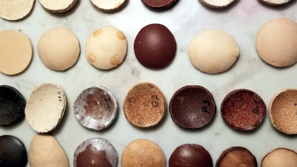
Making PCBs With A Cutting Plotter

[LudwigLabs] is creating PCBs using copper foil and a cutting plotter (vinyl cutter). In this approach, it’s an additive process where instead of removing copper from a copper-clad board, the traces are cut out of copper foil and transferred to a solid backing surface (cardboard, fiberglass, etc.).

While similar to the use of copper tape laid out by hand, as covered by us last year, the big advantage of using a cutting plotter is that it allows one to create much more complicated traces similar to those you would expect to see on a factory-made PCB. Since cutting plotters translate a 2D design into very precise movements of the cutting blade, this allows for sharp angles and significantly thinner traces, allows designs from EDA software like KiCad or Altium to be quickly translated to physical boards.

Enterprising hackers might consider the possibility of using this approach to make two-sided, and even multi-layered boards. The copper is produced separately from the substrate which opens up the potential for using uncommon materials like glass or paper to host the circuits. The main limitations are the transferring of (very delicate) copper structures and creating vias without damaging the traces.

As a comparison with traditional PCB fab processes, the photo exposure and etching (or laser exposure and etching) process requires the creation of masks, UV exposing a board, etching, cleaning and so on. The simplicity of copper foil traces has led to many experimenting with this approach. Would you want to use this additive process, or are there refinements or alterations you would make?

Brain Cell Electronics Explains Wetware Computing Power

Neural networks use electronic analogs of the neurons in our brains. But it doesn’t seem likely that just making enough electronic neurons would create a human-brain-like thinking machine. Consider that animal brains are sometimes larger than ours — a sperm whale’s brain weighs 17 pounds — yet we don’t think they are as smart as humans or even dogs who have a much smaller brain. MIT researchers have discovered differences between human brain cells and animal ones that might help clear up some of that mystery. You can see a video about the work they’ve done below.

Neurons have long finger-like structures known as dendrites. These act like comparators, taking input from other neurons and firing if the inputs exceed a threshold. Like any kind of conductor, the longer the dendrite, the weaker the signal. Naively, this seems bad for humans. To understand why, consider a rat. A rat’s cortex has six layers, just like ours. However, whereas the rat’s brain is tiny and 30% cortex, our brains are much larger and 75% cortex. So a dendrite reaching from layer 5 to layer 1 has to be much longer than the analogous neuron in the rat’s brain.

These longer dendrites do lead to more loss in human brains and the MIT study confirmed this by using human brain cells — healthy ones removed to get access to diseased brain cells during surgery. The researchers think that this greater loss, however, is actually a benefit to humans because it helps isolate neurons from other neurons leading to increased computing capability of a single neuron. One of the researchers called this “electrical compartmentalization.” Dig into the conclusions found in the research paper.

We couldn’t help but wonder if this research would offer new insights into neural network computing. We already use numeric weights to simulate dendrite threshold action, so presumably learning algorithms are making weaker links if that helps. However, maybe something to take away from this is that less interaction between neurons and groups of neurons may be more helpful than more interaction.

Watching them probe neurons under the microscope reminded us of probing on an IC die. There’s a close tie between understanding the brain and building better machines so we try to keep an eye on the research going on in that area.

Continue reading “Brain Cell Electronics Explains Wetware Computing Power”

With Grinning Keyboard And Sleek Design, This Synth Shows It All

Stylish! is a wearable music synthesizer that combines slick design with stylus based operation to yield a giant trucker-style belt buckle that can pump out electronic tunes. With a PCB keyboard and LED-surrounded inset speaker that resembles an eyeball over a wide grin, Stylish! certainly has a unique look to it. Other synthesizer designs may have more functions, but certainly not more style.

The unit’s stylus and PCB key interface resemble a Stylophone, but [Tim Trzepacz] has added many sound synthesis features as well as a smooth design and LED feedback, all tied together with battery power and integrated speaker and headphone outputs. It may have been originally conceived as a belt buckle, but Stylish! certainly could give conference badge designs a run for their money.

The photo shown is a render, but a prototype is underway using a milled PCB and 3D printed case. [Tim]’s Google photo gallery has some good in-progress pictures showing the prototyping process along with some testing, and his GitHub repository holds all the design files, should anyone want a closer look under the hood. Stylish! was one of the twenty finalists selected for the Musical Instrument Challenge portion of the 2018 Hackaday Prize and is therefore one of the many projects in the running for the grand prize!

New AVR-IOT Board Connects To Google

Readers of Hackaday are no strangers to using a microcontroller to push data to WiFi. Even before the ESP8266 there were a variety of ways to do that. Now Microchip is joining the fray with a $29 board called the AVR-IOT WG that contains an 8-bit ATmega4808, a WiFi controller, and hardware-based crypto chip for authenticating with Google Cloud.

The board has a section with a USB port for charging a battery and debugging that looks like it is made to cut away. There are a number of LEDs and buttons along with a light sensor and a temperature sensor. It feels like the goal here was to pack as many Microchip parts onto a single dev board as possible. You’ll find the ATmega4808 as the main controller, an ATWINC1510 WiFi controller (a castellated module reminiscent of the ESP8266), the ATECC608A cryptographic co-processor, MCP73871 LiPo charger, MIC33050 voltage regulator, and an MCP9808 temperature sensor. We can’t find much info about the “nEDBG Programmer/Debugger” chip. If you’ve used it on one of a handful of other dev board, let us know in the comments about off-board programming and other possible hacks.

Naturally, the board works with AVR Studio or MPLAB X IDE (Microchip bought Atmel, remember?). Of course, Atmel START or MPLAB Code Configurator can configure the devices, too. There’s also an AVR-IoT-branded website that lets you use Google cloud to connect your device for development. The headers along the top and bottom edges are compatible with MicroElektronika Click boards which will make anyone with a parts bin full of those happy.

Looks like you can pick up the Microchip boards now from the usual places. From reading what Microchip is saying, they would like to position this as the “IoT Arduino” — something someone without a lot of experience could pick up and use to pipe data into Google cloud. While that’s probably good, it isn’t that hard to use an ESP-device to do the same thing using the Arduino IDE and then you have a 32-bit processor and you can use whatever cloud vendor you want. Sure, it would be a little more work, so maybe that’s where this offering will appeal.

On the plus side, we really liked that there was a battery option with a charger already on board — it seems like that’s something we always have to add anyway. It may be buried in the documentation, but the user’s guide and the technical guide didn’t appear to have an average and maximum current draw specified, so battery life is an open question, although the video says “low power.”

Although it isn’t quite the same thing, we’ve seen ESP8266’s talk to Google servers for interfacing with Google Home. And while it is on the Amazon cloud, we’ve even seen a 6502 up there.

Continue reading “New AVR-IOT Board Connects To Google”

Custom LED Signage From Household Items

We’ll admit it: sometimes we overthink things. We imagine some of you are the same way; there seems to be something in the hacker mentality that drives us to occasionally over-engineer ideas to the point of unrecognizability. There’s nothing inherently wrong with this, but sometimes it does keep us from seeing easier solutions.

For example, the very slick looking personalized LED sign (Google Translate) that [Clovis Fritzen] recently wrote in to share with us. If we were tasked with creating something like this there would certainly have been a 3D printer and likely a CNC involved before all was said and done, and a few days later we’d still be working out the bugs in our OpenSCAD code. But his approach is very different. Fantastically simple and constructed largely from household items, this is a good project to keep the Junior Hackers entertained on a rainy weekend.

The first step of the process is to draw out the characters you want onto a piece of cardboard, and then carefully cut it out. If you’re worried that you’re not particularly artistic, this step will go a bit better if you print out the design and tape the paper over the cardboard to serve as a template. Once you’ve got your design cut out, you glue or tape a piece of standard printer paper over it. This is the face of the display; it just needs to be lit from behind.

If you wanted to make a sign that was just a single color and didn’t have individually addressable elements, then it would be enough to illuminate the whole cutout with a single light source. But where’s the appeal in that? As [Clovis] shows, you can get much better results by constructing a segmented box, with one LED in each cell. By wiring each LED to a pin on an Arduino or other microcontroller, you’ll have control over the color and brightness of each section of the sign.

Of course, if you’re not big on the whole cardboard aesthetic, you could even recreate this design with the aforementioned CNC and 3D printer. [Clovis] shows how the basic concept works, and that it can be scaled pretty easily depending on the kind of materials you have access to.

Google's Piano Genie

Piano Genie Trained A Neural Net To Play 88-Key Piano With 8 Arcade Buttons

Want to sound great on a Piano using only your coding skills? Enter Piano Genie, the result of a research project from Google AI and DeepMind. You press any of eight buttons while a neural network makes sure the piano plays something cool — compensating in real time for what’s already been played.

Almost anyone new to playing music who sits down at a piano will produce a sound similar to that of a cat chasing a mouse through a tangle of kitchen pots. Who can blame them, given the sea of 88 inexplicable keys sitting before them? But they’ll quickly realize that playing keys in succession in one direction will produce sounds with consistently increasing or decreasing pitch. They’ll also learn that pressing keys for different lengths of times can improve the melody. But there’s still 88 of them and plenty more to learn, such as which keys will sound harmonious when played together.

Piano Genie training architectureWith Pinao Genie, gone are the daunting 88 keys, replaced with a 3D-printed box of eight arcade-style buttons which they made by following this Adafruit tutorial. A neural network maps those eight buttons to something meaningful on the 88-key piano keyboard. Being a neural network, the mapping isn’t a fixed one-to-one or even one-to-many. Instead, it’s trained to play something which should sound good taking into account what was play previously and won`t necessarily be the same each time.

To train it they use data from the approximately 1400 performances of the International Piano e-Competition. The result can be quite good as you can see and hear in the video below. The buttons feed into a computer but the computer plays the result on an actual piano.

For training, the neural network really consists of two networks. One is an encoder, in this case a recurrent neural network (RNN) which takes piano sequences and learns to output a vector. In the diagram, the vector is in the middle and has one element for each of the eight buttons. The second network is the decoder, also an RNN. It’s trained to turn that eight-element vector back into the same music which was fed into the encoder.

Once trained, only the decoder is used. The eight-button keyboard feeds into the vector, and the decoder outputs suitable notes. The fact that they’re RNNs means that rather than learning a fixed one-to-many mapping, the network takes into account what was previously played in order to come up with something which hopefully sounds pleasing. To give the user a little more creative control, they also trained it to realize when the user is playing a rising or falling melody and to output the same. See their paper for how the turned polyphonic sound into monophonic and back again.

If you prefer a different style of music you can train it on a MIDI collection of your own choosing using their open-sourced model. Or you can try it out as is right now through their web interface. I’ll admit, I started out just banging on it, producing the same noise I would get if I just hammered away randomly on a piano. Then I switched to thinking of making melodies and the result started sounding better. So some music background and practice still helps. For the video below, the researcher admits to having already played for a few hours.

This isn’t the first project we’ve covered by these Google researchers. Another was this music synthesizer again using neural networks but this time with a Raspberry Pi. And if our discussion of recurrent neural networks went a bit over your head, check out our overview of neural networks.

Continue reading “Piano Genie Trained A Neural Net To Play 88-Key Piano With 8 Arcade Buttons”

Chiptunes In An Altoids Tin

For [Dejan]’s entry to the Musical Instrument Challenge in this year’s Hackaday Prize, he’s tapping into some of the great work that has been done over the years to bring bleeps and bloops to the masses. He’s building a drum machine, a bass synth, and an arpeggiator that fits in your pocket, in a handy form factor that fits in an Altoids tin. It’s the FATCAT Altoids Tin Mod Tracker.

This is a simple build meant to fit in an Altoids tin, so you’re not getting a whole lot of hardware here. There’s a battery, there’s a boost circuit, and there’s a single chip, an ATtiny84. This tiny little microcontroller is the heart of the box, able to provide a drum track with a kick, snare, and a closed and open high hat. There’s a bass with a simple square wave and portamento, and an arp track that can be used as a lead or arpeggiated chords. All of this is programmed in C and uploaded straight to the chip.

The ATtiny series of microcontrollers are fairly popular for various means and methods of creating square wave bleeps and bloops. We’ve seen them become a MIDI synth that fits inside a MIDI jack, and we’ve seen how much chiptune goodness you can fit in thirty two bytes of RAM. Cornell even had a spat of rickroll vandalism with a coin cell throwie built on an ATtiny85. Anything that puts more ATtiny chiptunes into the hands of more people is great in our books, and this Altoids tin synth is just the thing.

You can check out a demo of the FATCAT below.

Continue reading “Chiptunes In An Altoids Tin”