You’d be hard pressed to find a carpenter who didn’t own a hammer, or a painter that didn’t have a couple of brushes kicking around. Some tools are simply so fundamental to their respective craft that their ownership is essentially a given. The same could be said of the breadboard: if you’re working with electronics on the hobby or even professional level, you’ve certainly spent a decent amount of time poking components and wires into one of these quintessential prototyping tools.
There’s little danger that the breadboard will loose its relevance going forward, but if [Andrea Bianchi] and her team have anything to say about it, it might learn some impressive new tricks. Developed at the Korean Advanced Institute of Science and Technology, VirtualComponent uses augmented reality and some very clever electronics to transform the classic breadboard into a powerful mixed-reality tool for testing and simulating circuits. It’s not going to replace the $3 breadboard you’ve got hiding at the bottom of your tool bag, but one day it might be standard equipment in electronics classrooms.
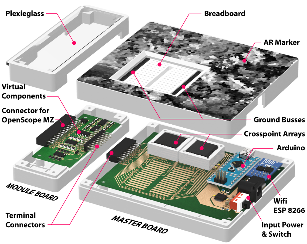
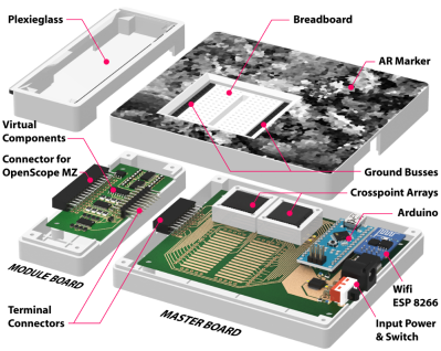 The short version is that VirtualComponent is essentially a dynamic breadboard. Holes in the same row are still electrically linked like in the classic breadboard, but with two AD75019 cross-point switch arrays and an Arduino in the base, it has the ability to virtually “plug in” components at arbitrary locations as selected by the user. So rather than having to physically insert a resistor, the user can simply tell the software to connect a resistor between two selected holes and the cross-point array will do the rest.
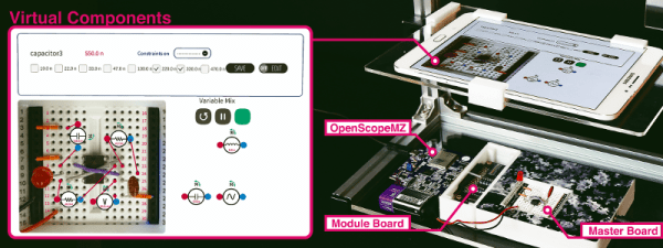
What’s more, many of those components can be either simulated or at least augmented in software. For example, by using AD5241 digital potentiometers, VirtualComponent can adjust the value of the virtual resistor. To provide variable capacitance, a similar trick can be pulled off using an array of real capacitors and a ADG715 digital switch to connect them together; essentially automating what the classic “Decade Box” does. In the demonstration video after the break, this capability is extended all the way out to connecting a virtual function generator to the circuit.
The whole system is controlled by way of an Android tablet suspended over the breadboard. Using the tablet’s camera, the software provides an augmented reality view of both the physical and virtual components of the circuit. With a few taps the user can add or edit their virtual hardware and immediately see how it changes the behavior of the physical circuit on the bench.
People have been trying to improve the breadboard for years, but so far it seems like nothing has really stuck around. Given how complex VirtualComponent is, they’ll likely have an even harder time gaining traction. That said, we can’t help but be excited about the potential augmented reality has for hardware development.
Continue reading “The Augmented Reality Breadboard Of The Future” →


 The first film follows the manufacture of the chain and anchor that would have been found on a ship around the turn of the twentieth century. One of the text frames mentions Netherton Works, allowing us to identify it as being filmed at
  The other video is contemporary, a How It’s Made look at chain manufacture. Here the chains involved are much smaller, everything is done by automated machinery, and once we have got over marveling at the intricacy of the process we can see that there is far more emphasis on the metallurgy. The wire is hard drawn before the chain is formed, and then hardened and annealed in a continuous process by a pair of induction heaters and water baths. I’m trying really hard to avoid a minor rant about the propensity of mass-market entertainment such as this for glossing over parts of the process. A keen eye notices that each link has become welded but we are not shown the machine that performs the task.