A recent French study indicates that the ancient Romans may have figured out how to deal with earthquakes by simply deflecting the energy of the waves using structures that resemble metamaterials. These are materials which can manipulate waves (electromagnetic or otherwise) in ways which are normally deemed impossible, such as guiding light around an object using a special pattern.
In a 2012 study, the same researchers found that a pattern of 5 meter deep bore holes in the ground was effective at deflecting a significant part of artificially generated acoustic waves. One of the researchers, [Stéphane Brûlé], noticed on an aerial photograph of a Gallo-Roman theater near the town of Autun in central France that its pattern of pillars bore an uncanny resemblance to this earlier experiment: a series of concentric (semi) circles with the distance between the pillars (or holes) decreasing nearer the center.
Further research using archaeological data of this theater site confirmed that it did appear to match up the expected pattern if one would have aimed to design a structure that could successfully deflect the acoustic energy from an earthquake. This raises the interesting question of whether this was a deliberate design choice, or just coincidence.
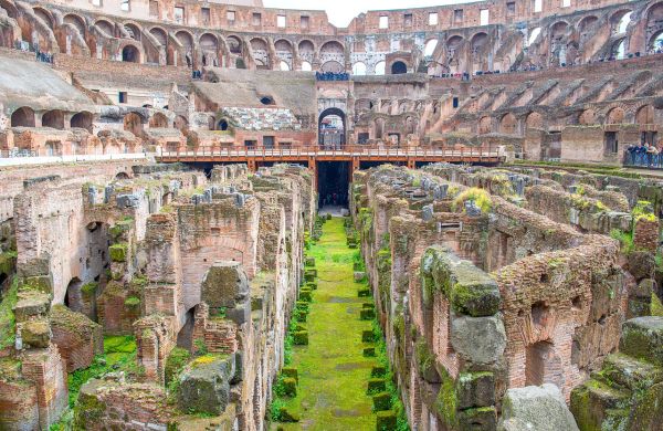
Additional research on the Colosseum in Rome and various other amphitheaters did however turn up the same pattern, which makes it seem like a deliberate choice by the Roman builders over a long period of time. With this pattern apparently capable of protecting a structure from the destructive effects of the acoustic waves generated by an earthquake, the remaining question is whether they discovered this pattern over time by observing damage to buildings and decided to implement it in new buildings.
Although we’ll likely never get an answer to that question, this discovery can however lead to improvements to individual buildings today, as well as entire cities, that may protect them against earthquakes and save countless lives that way.