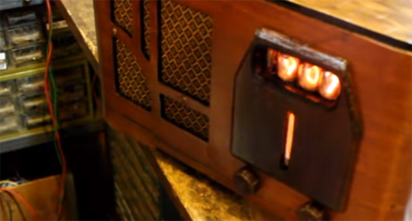
Getting An RF Low-Pass Filter Right

If you are in any way connected with radio, you will have encountered the low pass filter as a means to remove unwanted harmonics from the output of your transmitters. It’s a network of capacitors and inductors usually referred to as a pi-network after the rough resemblance of the schematic to a capital Greek letter Pi, and getting them right has traditionally been something of a Black Art. There are tables and formulae, but even after impressive feats of calculation the result can often not match the expectation.

The 30MHz low-pass filter, as QUCS delivered it.

Happily as with so many other fields, in recent decades the advent of affordable high-power computing has brought with it the ability to take the hard work out of filter design, Simply tell some software what the characteristics of your desired filter are, and it will do the rest. The results are good, and anyone can become a filter designer, but as is so often the case there remains a snag. The software calculates ideal inductances and capacitances for the desired cut-off and impedance, and in selecting the closest preferred values we modify the characteristics of the result and possibly even ruin our final filter. So it’s worth taking a look at the process here, and examining the effect of tweaking component values in this way.

The idealised graph produced by QUCS for our filter.

The filter we’re designing is simple enough, a 5th-order Bessel filter, and the software is the easy-to-use QUCS package on an Ubuntu Linux machine. Plug in the required figures and it spits out a circuit diagram, which we can then simulate to show a nice curve with a 3dB point right on 30MHz. It’s an extremely idealised graph, and experience has taught me that real-world filters using these designs have a lower-frequency cut-off point, but for our purposes here it’s a good enough start.

As previously mentioned, the component values are not preferred ones from a commercially available series, so I can’t buy them off the shelf. I can wind my own inductors, but therein lies a whole world of pain of its own and I’d rather not go there. RS, Mouser, Digikey, Farnell et al exist to save me from such pits of electronic doom, why on earth would I do anything else but buy ready-made?

My revised filter circuit with off-the-shelf component values.

So each of the components in the above schematic needs moving up or down a little way to a preferred value. What effect will that have on the performance of my filter? Changing each value and re-running the simulation shows us the graph changing subtly each time, and it can sometimes be a challenge to adjust them without destroying the filter entirely. Particularly with the higher-order filters with more components in the network you can observe the effect of individual components on the gradient at different parts of the graph, but as a rule of thumb making values higher reduces the cut-off frequency and making them lower increases it. In my case I always pick higher values for that reason: my nearest harmonic I wish to filter is at double the frequency so I have quite some headroom to play with.

The revised curve from the filter with preferred values.

Having replaced my component values with preferred ones I can run the simulation again, and I can see from the resulting graph that I’ve been quite fortunate in not damaging its characteristics too much. As expected the cut-off frequency has shifted up a little, but the same curve shape has been preserved without any ripples appearing or it being made shallower.

If I were using this filter with a real transmitter I would ensure that I designed it with a cut-off at least a quarter higher than the transmission frequency. In practice I find the cut-off to be sharper and lower than the simulation leads one to expect, and for example, were I to use this one with a 30 MHz transmitter I’d find it attenuated the carrier by more than I’d consider acceptable. It must also be admitted that changing the component values in this way will also change the impedance of the filter from the calculated 50 ohms, however in practice this does not seem to be significant enough to cause a problem as long as the value changes are modest.

We haven’t made this filter, but in the past we’ve featured another one I did make, and by coincidence it was in the same frequency range. When I wrote a feature on automating oscilloscope readings, the example I used was the characterisation of a 7th-order 30 MHz low-pass filter. It might even be one of the ones in the header image, pulled from my random bag of filter boards for the occasion.

What’s Behind The Door? An IoT Light Switch

We’re not sure who designed [Max Glenister]’s place, but they had some strange ideas about interior door positioning. The door to his office is right next to a corner, yet it opens into the room instead of toward the wall. Well, that issue’s been taken care of. But the architect and the electrician got the last laugh, because now the light switch is blocked by the open door.

Folks, this is the stuff that IoT is made for. [Max] here solved one problem, and another sprang up in its place. What better reason for your maiden voyage into the cloud than a terrible inconvenience? He studied up on IoT servo-controlled light switching, but found that most of the precedent deals with protruding American switches rather than the rockers that light up the UK. [Max] got what he needed, though. Now he controls the light with a simple software slider on his phone. It uses the Blynk platform to send servo rotation commands to a NodeMCU, which moves the servo horn enough to work the switch. It’s simple, non-intrusive, and it doesn’t involve messing with mains electricity.

His plan was to design a new light switch cover with mounting brackets for the board and servo that screws into the existing holes. That worked out pretty well, but the weight of the beefy servo forced [Max] to use a bit of Gorilla tape for support. He’s currently dreaming up ways to make the next version easily detachable.

Got those protruding American switches? [Suyash] shed light on that problem a while back.

No SD Card Slot? No Problem!

We feature hacks on this site of all levels of complexity. The simplest ones are usually the most elegant of “Why didn’t I think of that!” builds, but just occasionally we find something that is as much a bodge as a hack, a piece of work the sheer audacity of which elicits a reaction that has more of the “How did they get away with that! ” about it.

Such a moment comes today from [Robinlol], who has made an SD card socket. Why would you make an SD card socket when you could buy one is unclear, beyond that he didn’t want to buy one on an Arduino shield and considered manufacture his only option. Taking some pieces of wood, popsicle sticks, and paperclips, he proceeded to create a working SD card of such bodgeworthy briliance that even though it is frankly awful we still can’t help admiring it. It’s an SD card holder, and despite looking like a bunch of bent paperclips stuck in some wood, it works. What more could you want from an SD card holder?

Paperclips are versatile items. If an SD card holder isn’t good enough, how about using them in a CNC build?

PCB Junk Drawer Turned Into Blinky Mosaic

We’ve all got a box full of old PCBs, just waiting to be stripped of anything useful. [Dennis1a4] decided to do something with his, turning it into an attractive mosaic that he hung on the wall of his new workshop. But this isn’t just a pile of old PCBs: [Dennis1a4] decided to use the LEDs that were on many of the old boards, creating a blinky junk build. That’s kind of neat in itself, but he then decided to go further, building in an IR receiver so he could control the blinkiness, and a PIR sensor that detected when someone was near the mosaic.

This whole setup is controlled by an ATMega328p  that is driving a couple of PCF8575 port expanders that drive the LEDs. These blink in Morse code patterns. [Dennis1a4] also used an array of DIP switches on one of the boards to randomize the patterns, and wired in a pizeo buzzer on another board to make appropriate bleepy noises.

Continue reading “PCB Junk Drawer Turned Into Blinky Mosaic”

Digital Dining With Charged Chopsticks

You step out of the audience onto a stage, and a hypnotist hands you a potato chip. The chip is salty and crunchy and you are convinced the chip is genuine. Now, replace the ordinary potato chip with a low-sodium version and replace the hypnotist with an Arduino. [Nimesha Ranasinghe] at the University of Maine’s Multisensory Interactive Media Lab wants to trick people into eating food with less salt by telling our tongues that we taste more salt than the recipe calls for with the help of electrical pulses controlled by everyone’s (least) favorite microcontroller.

Eating Cheetos with chopsticks is a famous lifehack but eating unsalted popcorn could join the list if these chopsticks take hold and people want to reduce their blood pressure. Salt is a flavor enhancer, so in a way, this approach can supplement any savory dish.

Smelling is another popular machine hack in the kitchen, and naturally, touch is popular beyond phone screens. You have probably heard some good audio hacks here, and we are always seeing fascination stuff with video.

A Surprisingly Practical Numitron Watch

Regular Hackaday readers are surely familiar with Nixie tubes: the fantastically retro cold cathode display devices that hackers have worked into all manner of devices (especially timepieces) to give them an infusion of glowing faux nostalgia. But unfortunately, Nixie displays are fairly fragile and can be tricky to drive due to their high voltage requirements. For those who might want to work with something more forgiving, a possible alternative is the Numitron that uses incandescent filaments for each segment.

There hasn’t been a lot of prior-art that utilizes Numitrons, but that might be changing, given how fantastic this wristwatch created by [Dycus] looks. With a multi-day battery life, daylight readability, and relatively straightforward construction, the Filawatch is likely to end up being something of a reference design for future Numitron watches.

[Dycus] has gone through three revisions of the Filawatch so far, with probably at least one more on the way. The current version is powered by a ATmega328 microcontroller with dual 16-bit LED drivers to control the filaments in the KW-104S Numitron display modules. He’s also included an accelerometer to determine when the wearer is looking at the display, and even a light sensor to control the brightness of the display depending on the ambient light level.

If there’s a downside to Numitron displays, it’s their monstrous energy consumption. Just like in the incandescent light bulbs most of us have been ditching for LED, it takes a lot of juice to get that filament glowing. [Dycus] reports the display draws as much as 350 mA while on, but by lighting it up for only five seconds at a time it can be checked around 150 times before the watch needs to be recharged.

Its been a few years since we’ve seen a Numitron watch, and it’s interesting to see how the state of the art has advanced.

[via /r/electronics]

Hanging, Sliding Raspi Camera Adds Dimension To Octoprint

Are you using Octoprint yet? It’s so much more than just a way to control your printer over the internet, or to keep tabs on it over webcam when you’re off at work or fetching a beer. The 3D printing community has rallied around Octoprint, creating all sorts of handy plug-ins like Octolapse, which lets you watch the print blossom from the bed via time-lapse video.

Hackaday alum [Jeremy S Cook] wanted to devise a 3D-printable mount for a Raspi camera after finding himself inspired by [Tom Nardi]’s excellent coverage of Octoprint and Octolapse. He recently bought a wire shelving unit to store his printer and printer accessories, and set to work. We love the design he came up with, which uses the flexibility of the coolant hose to provide an endlessly configurable camera arm. But wait, there’s more! Since [Jeremy] mounted it to the rack with zip ties, the whole rig shimmies back and forth, providing a bonus axis for even more camera views. Slide past the break to see [Jeremy]’s build/demo video.

It’s great to be able to monitor a print from anywhere with internet access, but the camera is almost always set up for a tight shot on the print bed. How would you ever know if you’re about to run out of filament? For that, you need a fila-meter.

Continue reading “Hanging, Sliding Raspi Camera Adds Dimension To Octoprint”