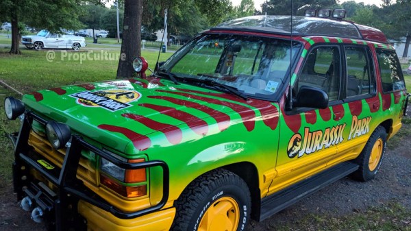
While you’d be hard pressed to find any serious figures on such things, we’d wager there’s never been a vehicle from a TV show or movie that has been duplicated by fans more than the Staff Jeeps from Jurassic Park. Which is no great surprise: not only do they look cool, but it’s a relatively easy build. A decent paint job and some stickers will turn a stock Wrangler into a “JP Jeep” that John Hammond himself would be proud of.
 While no less iconic, there are far fewer DIY builds of the highly customized Ford Explorer “Tour Vehicles”. As a rather large stretch of the film takes place within them, the interiors were much more detailed and bears little resemblance to the stock Explorer. Building a truly screen accurate Jurassic Park Tour Vehicle was considered so difficult that nobody has pulled it off since the movie came out in 1993. That is until [Brock Afentul] of PropCulture decided to take on the challenge.
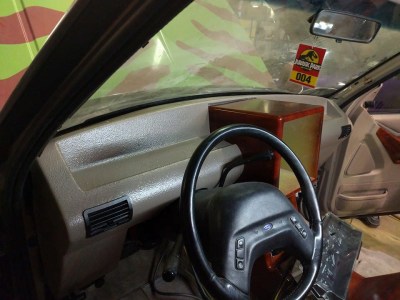
In an epic journey spanning five years, [Brock] has created what he believes is the most accurate Jurassic Park Tour Vehicle ever produced; and looking at the side by side shots he’s done comparing his Explorer to the ones from the movie, it’s hard to disagree. A massive amount of work went into the interior, leaving essentially nothing untouched. While previous builds have tried to modify the stock dashboard to look like the one from the movie, he built a completely new dash from MDF and foam and coated it in fiberglass. The center console featuring the large display was also faithfully reproduced from the movie, and runs screen accurate animations, maps, and tour information. The seats also had to be replaced, multiple times in fact, as he had a considerable amount of trouble getting somebody to upholster them to his standards.
 But perhaps the most difficult component of all was the clear acrylic roof bubble. These were critical to filming the movie, as they not only let the viewer see down into the Tour Vehicles but also let the characters see out during the iconic tyrannosaurus attack. But because the roof bubble was created only for the movie and never existed as a real aftermarket product, it usually gets ignored in Tour Vehicle builds. It’s simply too difficult to produce for most people. The omission of the bubble was always considered a case of artistic license; in the same way nobody expects a replica DeLorean from Back to the Future to actually fly or travel through time.
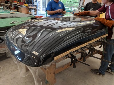
But [Brock] wanted to take his Tour Vehicle all the way, so he partnered up with a local glass shop that let him rent time in their oven so he could heat up acrylic sheets. Once heated to the appropriate temperature, they could be removed and wrapped around a mold to make the bubble. The process took weeks to perfect, but in the end he and a few friends got the hang of it and were able to produce a gorgeous roof bubble that they fitted to the already very impressive Explorer.
While previous Jurassic Park Tour Vehicle replicas were unquestionably awesome, this build really does take it to the next level. Short of equipping the garage with a movie-accurate super computer, it’s hard to see how the bar can get any higher.