DEF CON 24 is still about two weeks away but we managed to get our hands on a hardware badge early. This is not the official hardware — there’s no way they’d let us leak that early. Although it may be unofficial in the sense that it won’t get you into the con, I’m declaring the AND!XOR badge to be officially awesome. I’ll walk you through it. There’s also a video below.
Over the past several years, building your own electronic badge has become an impromptu event. People who met at DEF CON and have been returning year after year spend the time in between coming up with great ideas and building as many badges as they can leading up to the event. This is how I met the trio who built this badge — AND!XOR, Andrew Riley, and Jorge Lacoste — last year they invited me up to their room where they were assembling the last of the Crypto Badges. Go check out my guide to 2015 Unofficial DEF CON badges for more on that story (and a video of the AM transmissions that badge was capable of).
The outline is this year’s badge is of course Bender from Futurama. Both eyes are RGB LEDs, with another half dozen located at different points around his head. The microcontroller, an STM32F103 ARM Cortex-M0 Cortex-M3, sits in a diamond pattern between his eyes. Above the eyes you’ll find 16 Mbit of flash, a 128×64 OLED screen, and a reset button. The user inputs are five switches and the badge is powered by three AA batteries found on the flip side.
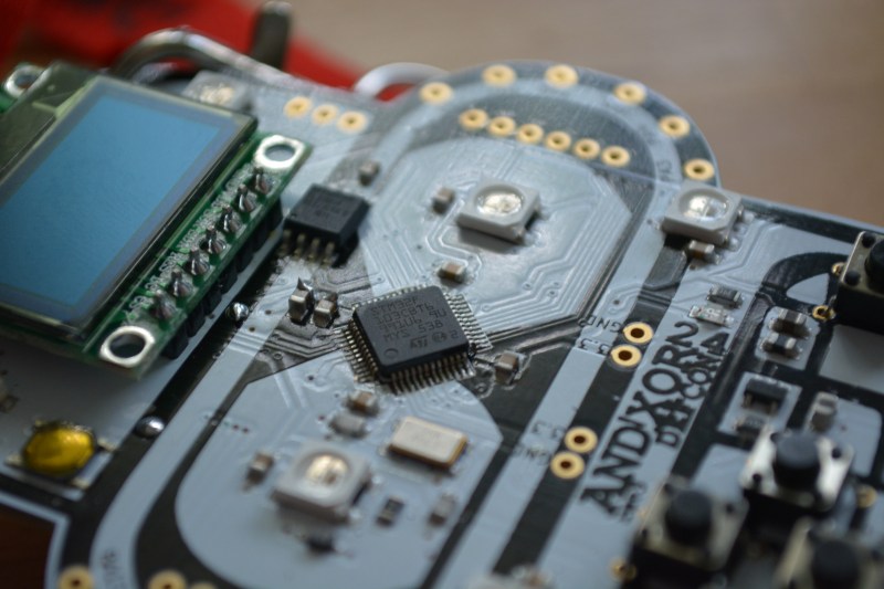
That alone makes an interesting piece of hardware, but the RFM69W module makes all of the badges interactive. The spring coming off the top of Bender’s dome is a coil antenna for the 433 MHz communications. I only have the one badge on hand so I couldn’t delve too deeply what interactive tricks a large pool of badges will perform, but the menu hints at a structure in place for some very fun and interesting applications.
Continue reading “Hands-on The AND!XOR Unofficial DEF CON Badge” →