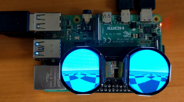
Virtual Reality always seemed like a technology just out of reach, much like nuclear fusion, the flying car, or Linux on the desktop. It seems to be gaining steam in the last five years or so, though, with successful video games from a number of companies as well as plenty of other virtual reality adjacent technology that seems to be picking up steam as well like augmented reality. Another sign that this technology might be here to stay is this virtual reality headset made for mice. Continue reading “Mice Play In VR”→
Raspberry Pi has just introduced a new camera module in the high-quality camera format. For the same $50 price you would shell out for the HQ camera, you get roughly eight times fewer pixels. But this is a global shutter camera, and if you need a global shutter, there’s just no substitute. That’s a big deal for the Raspberry Pi ecosystem.
Global vs Rolling
Most cameras out there today use CMOS sensors in rolling shutter mode. That means that the sensor starts in the upper left corner and rasters along, reading out exposure values from each row before moving down to the next row, and then starting up at the top again. The benefit is simpler CMOS design, but the downside is that none of the pixels are exposed or read at the same instant.
It’s fair to say that among the new product launches we see all the time, anything new from the folks at Raspberry Pi claims our attention. It’s not that their signature Linux single-board computers (SBCs) are necessarily the best or the fastest hardware on paper, but that they’re the ones with meaningful decade-plus support. Add to that their RP2040 microcontroller and its associated Pico boards, and they’re the one to watch.
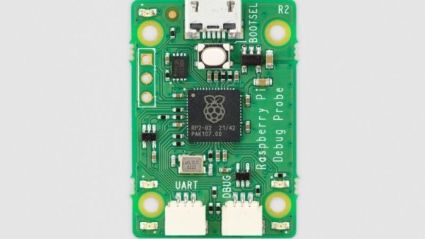
Today we’ve got news of a new Pi, not a general purpose computer, but useful nevertheless. The Raspberry Pi Debug Probe is a small RP2040-based board that provides a SWD interface for debugging any ARM microcontroller as well as a more generic USB to UART interface.
The article sums up nicely what this board does — it’s for bare metal ARM coders, and it uses ARM’s built-in debugging infrastructure. It’s something that away from Hackaday we’ve seen friends using the 2040 for as one of the few readily available chips in the shortage, and it’s thus extremely convenient to have readily available as a product.
So if you’re a high level programmer it’s not essential, but if you’re really getting down to the nuts-and-bolts of an ARM microcontroller then you’ll want one of these. Of course, it’s by no means the first SWD interface we’ve seen, here’s one using an ESP32.
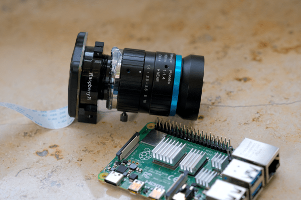
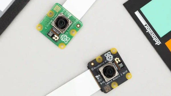
There’s nothing new about a Pi camera module as they’ve been available for years in both official and third party forms, so to be noteworthy the new one has to offer something a bit special. It uses a 12 megapixel sensor, and is available both in autofocus and wide angle versions in both standard and NoIR variants. Wide angle and autofocus modules may be new in the official cameras, but these are both things which have been on the third-party market for years.
So if an autofocus camera module for your Pi isn’t that new, what can we bring to a review that isn’t simply exclaiming over the small things? Perhaps it’s better instead to view the new camera in the context of the state of the Pi camera ecosystem, and what better way to do that than to turn a Pi and some modules into a usable camera! Continue reading “Do You Need The Raspberry Pi Camera Module V3?”→
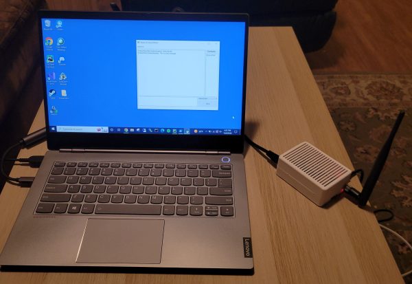
The Internet has allowed us to communicate more easily than ever before, and thanks to modern cell-phone networks, we don’t even have to be tied down to a hard line anymore. But what if you want something a little more direct? Maybe you’re in an area with no cell-phone coverage, or you don’t want to use public networks for whatever reason. For those cases, you might be interested in this Secure Communication Network project by [Thomas].
By leveraging the plug-and-play qualities of the Raspberry Pi 4 and the Adafruit LoRa Radio Bonnet, [Thomas] has been able to focus on the software side of this system that really turns these parts into something useful.
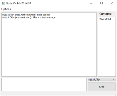
Messages are tagged as “authenticated” when a shared hashing code is included in the message
Rather than a simple point-to-point radio link, a mesh network is built up of any transceivers in range, extending the maximum distance a message can be sent, and building in resilience in case a node goes down. Each node is connected to a PC via Ethernet, and messages are distributed via a “controlled flooding” algorithm that aims to reduce unnecessary network congestion from the blind re-transmission of messages that have already been received.
Security is handled via RSA encryption with 256-byte public/private keys and additional SHA256 hashes for authentication.
The packet-size available through the LoRa device is limited to 256 bytes, of which 80 bytes are reserved for headers. To make matters worse, the remaining 176 bytes must contain encrypted data, which is almost always more lengthy than the raw message it represents. Because of this, longer messages are fragmented by the software, with the fragments sent out individually and re-assembled at the receiving end.
If you’re in need of a decentralized secure radio communications system, then there’s a lot to like about the project that [Thomas] has documented on his Hackaday.io page. He even includes an STL file for a 3D printed case. If you need to send more than text, then this Voice-over-LoRa Mesh Network project may be more your style.
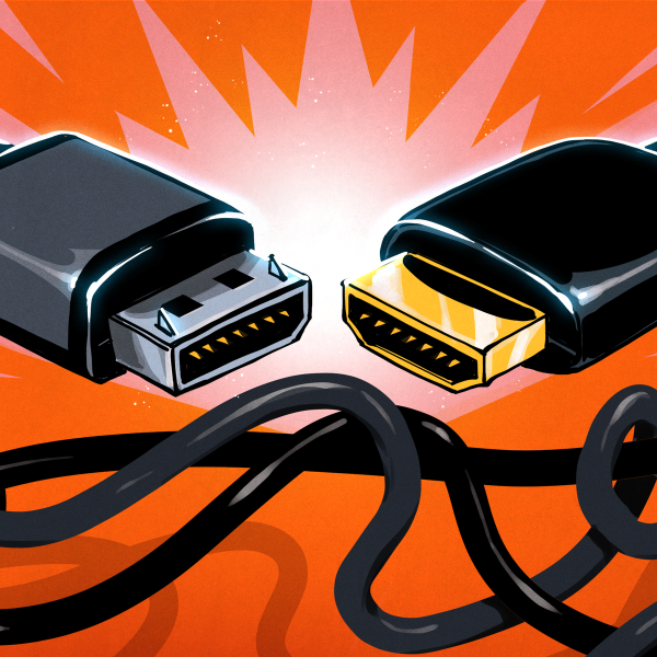
If you’ve been following along our USB-C saga, you know that the CC wire in the USB-C cables is used for communications and polarity detection. However, what’s not as widely known is that there are two protocols used in USB-C for communications – an analog one and a digital one. Today, let’s look at the analog signalling used in USB-C – in part, learn more about the fabled 5.1 kΩ resistors and how they work. We’ll also learn about emarkers and the mysterious entity that is VCONN!
USB-C power supply expects to sense a certain value pulldown on the CC line before it provides 5 V on VBUS, and any higher voltages have to be negotiated digitally. The PSU, be it your laptop’s port or a charger, can detect the pulldown (known as Rd) because it keeps a pullup (known as Rp) on the CC line – it then checks if a voltage divider has formed on CC, and whether the resulting voltage is within acceptable range.
If you plug a device that doesn’t make a pulldown accessible through the CC wire in the cable, your device will never get power from a USB-C port, and would only work with a USB-A to USB-C cable. Even the smarter devices that can talk the digital part of USB-C are expected to have pulldowns, it’s just that those pulldowns are internal to the USB-C communication IC used. A USB-C port that wants to receive power needs to have a pulldown.
This part is well-known by now, but we’ve seen lack-of-resistor failures in cheap devices aplenty, and the colloquial advice is “add 5.1 kΩ resistors”. You might be afraid to think it’s so simple, but you’d be surprised. Continue reading “All About USB-C: Resistors And Emarkers”→
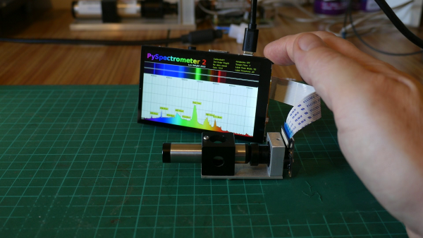
Here at Hackaday, we love to see projects re-visited and updated after we’ve covered them on the site. It’s always exciting to see what the creators come up with next, and this Pi-Based Spectrometer project is a great example of that.
[LesWright] found himself with a problem when the new version of Raspberry Pi operating system was released (Bullseye), and it broke some functionality on his original software. Rather than just fix the issues, [Les] chose to rewrite the software more dramatically and has ended up with a much more capable spectrometer that is able to match professional devices costing many times more.
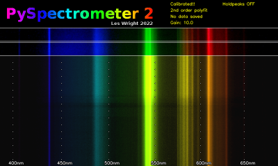
Screenshot of Waterfall Display for PySpectrometer 2
By using multi-wavelength calibration and polynomial regression data, the new version is much more accurate and can now resolve wavelengths down to +/- 1nm.
The whole project is now written in OpenCV, and there’s a nifty new waterfall spectrum display, that will show changes in measured spectra over time.
A low-cost benchtop spectroscope is coupled to a RaspberryPi Camera via a CCTV zoom lens and the whole setup is mounted to a small block of aluminium for thermal and mechanical stability. The spectroscope is pointed at a fluorescent lamp and the user is guided through a calibration routine to tune the software to the hardware.
We’re impressed with the precision [Les] has achieved with his builds, and the write-up is sufficiently detailed to allow others to follow in his footsteps. We’d love to see if readers build one themselves, and what they use them for!