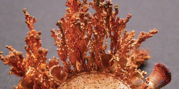
Motion Light In Dark Stairwell Brightens Trips To The Basement

WARNNG: Walking around in the dark could be dangerous to your health! You may bump into something or worse, take a tumble down the stairs. Safety conscious [Ganesh] has come up with a solution for us folks too lazy to manually turn on a light. It’s a simple light controlled by a motion sensor that anyone can put together.

The meat and potatoes of the build is an off-the-shelf motion sensor, the same kind that is used in a home security system. We humans emit infrared energy and that is just what this sensor ‘sees’. The motion sensor is powered by 12 VDC and has a pair of DC output leads that are used to control a relay. [Ganesh] used an standard hobby relay board with built in power spike protection diode and transistor to supply the current required to trip the relay. Closing the relay sends mains power to the AC light bulb. Both the triggering threshold and the ‘on’ time are controlled by potentiometers integrated with the motion sensor.

Check the video out after the break of the device working its magic and lighting the way to [Ganesh’s] basement dungeon…

Continue reading “Motion Light In Dark Stairwell Brightens Trips To The Basement”

Simple Superheterodyne SW Receiver Harks Back Almost 100 Years

Early radio receivers worked on a principle called Tuned Radio frequency (TRF), patented in 1916. They weren’t very easy to use, requiring each stage to be tuned to the same frequency (until ganged capacitors made that a bit easy). The Superheterodyne design, devised in 1918, was superior, but more expensive at that time. Cost considerations led adoption of the Superhet design to lag behind TRF until almost 1930. Since then, until quite recently, the Superhet design has been at the heart of a majority of commercial radio receivers. Direct Conversion Receivers were devised around 1930, but required elaborate phase locked loops which restricted their use in commercial receivers. The point of all this background is that the Superhet design has served very well for more than 90 years, but will soon be rendered redundant once Software defined Radio (SDR) becomes ubiquitous. Which is why this study of the simple Superheterodyne shortwave receiver deserves closer study.

[Dilshan] built this two transistor and two IF transformer based superheterodyne radio designed to receive 13m to 41m bands. The whole build is assembled on a breadboard, making it easy to teach others to experiment. [Dilshan] offers very useful insights into antenna, rod coil and IF transformer parameters. To dive in to Radio architecture, check this post on Amateur Radio. And if you would like to get a closer look at Antique Radios, check this post on Restoring Antique Radios.

Binary Wristwatch

Open Source Binary Wristwatch Is Professional Quality

If you want to proclaim to the world that you’re a geek, one good way to go about it is to wear a wristwatch that displays the time in binary. [Jordan] designs embedded systems, and he figured that by building this watch he could not only build up his geek cred but also learn a thing or two about working with PIC microcontrollers for low power applications. It seems he was able to accomplish both of these goals.

The wristwatch runs off of a PIC18F24J11 microcontroller. This chip seemed ideal because it included a built in real-time clock and calendar source. It also included enough pins to drive the LEDs without the need of a shift register. The icing on the cake was a deep sleep mode that would decrease the overall power consumption.

The watch contains three sets of LEDs to display the information. Two green LEDs get toggled back and forth to indicate to the user whether the time or date is being displayed. When the time is being displayed, the green LED toggles on or off each second. The top row of red LEDs displays either the current hour or month. The bottom row of blue LEDs displays the minutes or the day of the month. The PCB silk screen has labels that help the user identify what each LED is for.

The unit is controlled via two push buttons. The three primary modes are time, date, and seconds. “Seconds” mode changes the bottom row of LEDs so they update to show how many seconds have passed in the current minute. [Jordan] went so far as to include a sort of animation in between modes. Whenever the mode is changed, the LED values shift in from the left. Small things like that really take this project a step further than most.

The board includes a header to make it easy to reprogram the PIC. [Jordan] seized an opportunity to make extra use out of this header. By placing the header at the top of the board, and an extra header at the bottom, he was able to use a ribbon cable as the watch band. The cable is not used in normal operation, but it adds that extra bit of geekiness to an already geeky project.

[Jordan] got such a big response from the Internet community about this project that he started selling them online. The only problem is he sold out immediately. Luckily for us, he released all of the source code and schematics on GitHub so we can make our own.

Penny And Paper Clip Heat Sinks

A bunch of audio heads over at the Head-Fi forum were discussing handy and quick heat sinking methods, leading to much speculation and conjecture. This finally prompted [tangentsoft] to take matters in his own hands and run some tests on DIY Heat Sinks.

The question that sparked this debate was if a paper clip is a good enough heat sink to be used for a TO220 package. Some folks suggested copper pennies (old ones minted 1981 and earlier – the new ones are zinc with copper plating and won’t help much). [tangentsoft] built a jig to test six LM317 regulators in constant current mode set to 0.125A and 2w dissipation. The six configurations were a paper clip, a single penny bolted to the regulator, a regular Aavid TO220 heat sink, a set of 4 pennies bolted, a single penny epoxy glued and finally a single penny soldered directly to the regulator.

The results were pretty interesting. The paper clip scored better than any of the single pennies! The quad-penny and the Aavid heat sink fared above all the other configurations, and almost at par with each other. [tangentsoft] posts his review of each configurations performance and also provides details of his test method, in case someone else wants to replicate his tests to corroborate the results. He tested each configuration independently for one hour, gathering just over 10000 readings for each setup. Other nearby heat sources were turned off, and he placed strategic barriers around the test circuit to isolate it from the effects of other cooling / heating sources. He even removed himself from the test area and monitored his data logging remotely from another room. When he noticed a couple of suspect deviations, he restarted the test.

[tangentsoft] put all the data through Mathematica and plotted his results for analysis, available at this link [pdf, 2.8MB]. So the next time you want to heat sink a regulator for cheap, just hunt for Clippy in your box of office supplies. Do remember that these methods will work for only a couple of watts dissipation. If you would like to cast and build your own heat sinks out of aluminum, check out this post about DIY Aluminum heat sink casting. And if you need help calculating heat sink parameters, jump to 12:00 minutes in this video from [Dave]’s EEVBlog episode on Dummy loads and heat sinks.

Thanks to [Greg] for sending in this tip.

photo booth

Reach Out And Touch Someone With WiFi Photo Booth

[kitesurfer1404] put together a nice looking vintage photobooth with WiFi capability. He’s using an arduino to monitor the state of the buttons, LED lighting control, seven segment display AND the DSLR camera. He then uses a Raspberry Pi to control imagine processing and to provide scaling and other effects, which can take up to 20 seconds per image. The Pi runs in WiFi Access Point mode, so anyone with a WiFi capable device can connect to the photo booth and view the images.

We’ve seen some interesting twists on photo booths before. But [kitesurfer1404’s] vintage style makes his stand out all on its own. He designed the graphics with Inkscape and printed them on thick paper. He then soaked the graphics in tea for several hours and dried then for several more days to get that nice rustic look.

Be sure to check out [kitesurfer1404’s] site for full details and an assortment of high resolution images of his project.

Optimized Molds With 3D Printing

[Florian] has a few arcade games and MAME machines, and recently he’s been trying to embed objects in those hard plastic spheres on the end of joysticks. A common suggestion is to 3D print some molds, but even though that’s a great idea in theory the reality is much different: you’re going to get layer lines on the casting, and a mirror finish is impossible.

No, a silicone mold is the way to do this, but here 3D printing can be used to create the mold for the silicone. Instead of a few pieces of hot glued cardboard or a styrofoam cup, [Florian] is 3D printing a a container to hold the liquid silicone around the master part.

After printing a two-piece part to hold both halves of a silicon mold, [Florian] put the master part in, filled it up with silicone, and took everything apart. There were minimal seam lines, but the end result looks great.

In addition to making a 3D printed mold container, [Florian] is also experimenting with putting 3D printed parts inside these joystick balls. The first experiment was a small 3D printed barrel emblazoned with the Donkey Kong logo. This turned out great, but there’s a fair bit of refraction that blows out all the proportions. Further experiments will include a Pac-Man, a skull, and a rose, to be completed whenever [Florian] gets a vacuum chamber.

Dirt Cheap Motor Balancing And Vibration Analysis

Ever the enterprising hacker and discerning tool aficionado, [Chris] knows the importance of “feel”. As a general rule, cheap tools will shake in your hand because the motors are not well-balanced. He wanted a way to quantify said feel on the cheap, and made a video describing how he was able to determine the damping of a drill using a few items most people have lying around: an earbud, a neodymium magnet, scrap steel, and Audacity.

He’s affixed the body of the drill to a cantilevered piece of scrap steel secured in a vise. The neodymium magnet stuck to the steel interrupts the magnetic field in the earbud, which is held in place with a third hand tool. [Chris] taped the drill’s trigger down and controls its speed a variac. First, [Chris] finds the natural frequency of the system using Audacity’s plot spectrum, and then gets the drill to run at the same speed to induce wobbling at different nodes. As he explains, one need not even use software to show the vibration nodes—a laser attached to the system and aimed at a phosphorescent target will plot the sine wave.

Just for fun, he severely unbalances the drill to find the frequencies at which the system will shake itself apart. Check it out after the break.

Continue reading “Dirt Cheap Motor Balancing And Vibration Analysis”