Two weekends ago was the Bay Area Maker Faire, and lacking a venue to talk to people who actually make things, we had a meetup at a pub. This brought out a ton of interesting people, and tons of interesting demos of what these people were building. By either proclivity or necessity, most of these demos were very blinkey. The demo [Grant McGregor] from Monterey Community College brought was not blinkey, but it was exceptionally cool. He’s levitating objects in paramagnetic liquids with permanent magnets.
Levitating objects in a paramagnetic solution around a magnetic field has been an intense area of research for the Whitesides Research Group for a few years now, with papers that demonstrate methods of measuring the density of objects in a paramagnetic solution and fixing diamagnetic objects inside a magnetic field. [Grant] is replicating this research with things that can be brought to a bar in a small metal box – vials of manganese chlorate with bits of plastic and very strong neodymium magnets. The bits of plastic in these vials usually float or sink, depending on exactly what plastic they’re made of. When the paramagnetic solution is exposed to a magnetic field, the density of the solution changes, making the bits of plastic sink or float.
It’s a bizarre effect, but [Grant] mentioned a nurd rage video that shows the effect very clearly. [Grant]’s further experiments will be to replicate the Whitesides Research Group’s experiment to fix a diamagnetic object inside a magnetic field. As for any practical uses for this effect, you might be able to differentiate between different types of plastic (think 3D printing filament) with just a vial of solution and a strong magnet.
[Grant] was heading out of the pub right when I ran into him, but he did stick around long enough to run into the alley behind the pub and record an interview/demo. You can check that out below.
Continue reading “Levitating Objects In Paramagnetic Liquids”
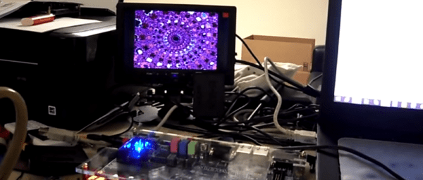
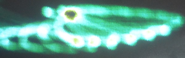
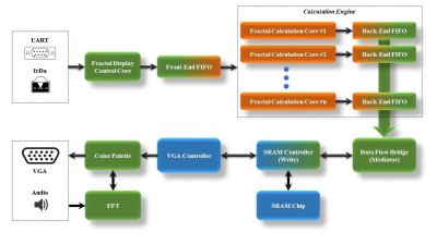 On the FPGA, a custom calculation engine, running at up to 150 MHz, does the math to generate the fractal. A Fast Fourier transform decomposes the audio input into frequencies, which are used to control the colors of the output image.


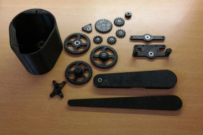 The 3D printed parts were designed by [dragonator] himself. All of the design files are available