Only 80s kids will remember actual hair metal with the meedley-mees way up high on the fret board, and in the 80s, fret boards got longer. Twenty one or twenty two frets on a guitar weren’t good enough, and you needed the full two octaves of twenty four frets. As with anything, more is better, so [Said Too Much] decided to add frets to his guitar. Yes, you can do that, and it actually doesn’t sound too bad, all things considering.
A few things to cover before going over this build. This did not start out as an experiment to extend the fretboard of a guitar. This started out as a soprano guitar build; this would be the inverse of a baritone guitar — instead of an extended scale length and heavier strings to play a fourth or fifth below a regular guitar, this soprano guitar would have a shorter scale length and lighter gauge strings to play a fourth or fifth above a regular guitar. After a few calculations and some calls to companies that make very, very thin guitar strings, this project morphed into a 3/4 scale guitar (a 23″ scale length, although I question that scale length being actually 3/4 scale) and a set of strings that used 0.07″ strings.
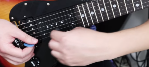
Since a soprano guitar is pretty much just like a normal guitar with more frets, this project also got an extended, 3D printed fretboard. Why? Because. The stock pick guard was modeled and printed out in PLA, removing the neck and middle pickups. Then, an ‘extended fret board adapter’ of sorts was slotted in behind the strings. This gives the guitar 38 frets, a full third of them being printed in PLA.
The burning question: does a 3D printed fret board work? Yes, kind of. If you can get your fingers in between the frets, you can absolutely play the 36th fret on this guitar. It’s not for everybody, obviously, and PLA printed frets will never be as good as polished metal frets. But it is an interesting experimental technique for stringed instruments we haven’t seen before. Check out the video below.