Retrotechtacular: Forces Acting On An Airfoil

floating film title We’ve probably all experimented with a very clear demonstration of the basic principles of lift: if you’re riding in a car and you put your flattened hand out the window at different angles, your hand will rise and fall like an airplane’s wing, or airfoil. This week’s Retrotechtacular explains exactly how flight is possible through the principles of lift and drag. It’s an Army training documentary from 1941 titled “Aerodynamics: Forces Acting on an Air Foil“.

What is an airfoil? Contextually speaking, it’s the shape of an airplane’s wing. In the face of pressure differences acting upon their surfaces, airfoils produce a useful aerodynamic reaction, such as the lift that makes flight possible. As the film explains, the ideas of lift and drag are measured against the yardstick of relative wind. The force of this wind on the airfoil changes according to the acute angle formed between the airfoil and the direction of the air flow acting upon it. As you may already know, lift is measured at right angles to the relative wind, and drag occurs parallel to it. Lift is opposed by the weight of the foil, and drag by tension.
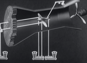
wind tunnel testing

Airfoils come in several types of thicknesses and curvatures, and the film shows how a chord is derived from each shape. These chords are used to measure and describe the angle of attack in relation to the relative wind.

The forces that act upon an airfoil are measured in wind tunnels which provide straight and predictable airflow. A model airplane is supported by wires that lead to scales. These scales measure drag as well as front and rear lift.

In experimenting with angles of attack, lift and drag increase toward what is known as the stalling angle. After this point, lift decreases abruptly, and drag takes over. Lift and drag are proportional to the area of the wing, the relative wind velocity squared, and the air density. When a plane is in the air, drag is a retarding force that equals the thrust of the craft, or the propelling force.
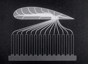
monometer tubesAirfoil models are also unit tested in wind tunnels. They are built with small tubes running along many points of the foil that sit just under the surface. The tubes leave the model at a single point and are connected to a bank of manometer tubes. These tubes compare the pressures acting on the airfoil model to the reference point of atmospheric pressure. The different liquid levels in the manometer tubes give clear proof of the pressure values along the airfoil. These levels are photographed and mapped to a pressure curve. Now, a diagram can be made to show the positive and negative pressures relative to the angle of attack.

In closing, we are shown the effects of a dive on lift as an aircraft approaches and reaches terminal velocity, and that lift is attained again by pulling slowly out of the dive. Remember that the next time you fly your hand-plane out the window.

Continue reading “Retrotechtacular: Forces Acting On An Airfoil”
Developed On Hackaday: Beta Testers And Automated Testing

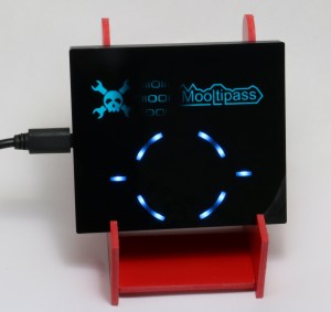
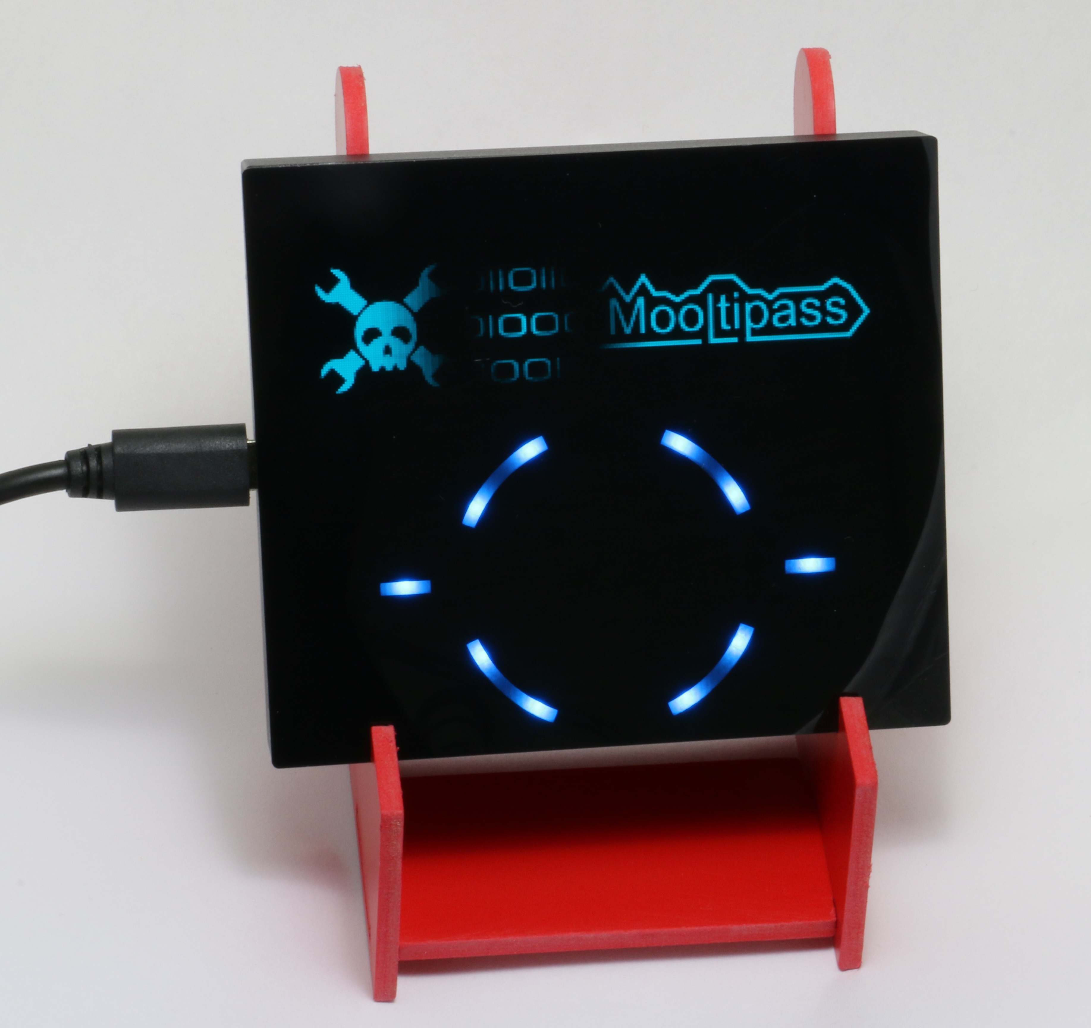
Mooltipass with Holder

At Hackaday we believe that your encrypted vault containing your credentials shouldn’t be on a device running several (untrusted) applications at the same time. This is why many contributors and beta testers from all over the globe are currently working on an offline password keeper, aka the Mooltipass.

Today we’re more than happy to report that all of our 20 beta testers started actively testing our device as they received the v0.1 hex file from the development team. Some of them had actually already started a few days before, as they didn’t mind compiling our source files located on our github repository and using our graphics generation tools. We are therefore expecting (hopefully not) many bug reports and ways to improve our device. To automatize website compatibility testing, our beta tester [Erik] even developed a java based tool that will automatically report non-working pages found inside a user generated list. You may head here to watch a demonstration video.

Thumbnail that say The Hacklet

Hacklet #11- Cameras

11

We preempt this week’s Hacklet to bring you an important announcement.

Hackaday.io got some major upgrades this week. Have you checked out The Feed lately? The Feed has been tweaked, tuned, and optimized, to show you activity on your projects, and from the hackers and projects you follow.

We’ve also rolled out Lists! Lists give you quick links to some of .io’s most exciting projects. The lists are curated by Hackaday staff. We’re just getting started on this feature, so there are only a few categories so far. Expect to see more in the coming days.

Have a suggestion for a list category? Want to see a new feature?  Let us know!

Now back to your regularly scheduled Hacklet

There are plenty of cameras on Hackaday.io, from complex machine vision systems to pinhole cameras. We’re concentrating on the cameras whose primary mission is to create an image. It might be for art, for social documentation, or just a snapshot with friends.

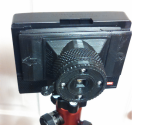
pinstax[theschlem] starts us off with Pinstax, a 3D Printed Instant Pinhole Camera. [theschlem] is using a commercial instant film camera back (the back for a cheap Diana F+) and 3D printing his own pinhole and shutter. He’s run into some trouble as Fuji’s instant film is fast, like ISO 800 fast. 3 stops of neutral density have come to the rescue in the form of an ND8 filter. Pinstax’s pinhole is currently 0.30mm in diameter. That translates to just about f/167. Nice!

largeformat

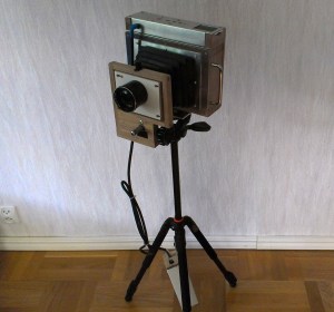
Next up is [Jimmy C Alzen] and his Large Format Camera. Like many large format professional cameras, [Jimmy’s] camera is designed around a mechanically scanned linear sensor. In this case, a TAOS TSL1412S. An Arduino Due runs the show, converting the analog output from the sensor to digital values, stepping the motor, and displaying images in progress on an LCD. Similar to other mechanically scanned cameras, this is no speed demon. Images in full sunlight take 2 minutes. Low light images can take up to an hour to acquire.

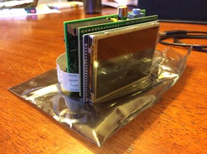
democracy[Jason’s] Democracycam aims to use open source hardware to document protests – even if the camera is confiscated. A Raspberry Pi, Pi Cam module, and a 2.8″ LCD touchscreen make up the brunt of the hardware of the camera. Snapping an image saves it to the SD card, and uses forban to upload the images to any local peers. The code is in python, and easy to work with. [Jason] hopes to add a “panic mode” which causes the camera to constantly take and upload images – just in case the owner can’t.

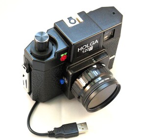
digiholgaThe venerable Raspberry Pi also helps out in [Kimondo’s] Digital Holga 120d. [Kimondo’s] fit a Raspberry Pi model A, and a Pi camera, into a Holga 120D case. He used the Slice of pi prototype board to add a GPIO for the shutter release button, a 4 position mode switch, and an optocoupler for a remote release. [Kimondo] even added a filter ring so he can replicate all those instagram-terrific filters in hardware. All he needs is to add a LiPo battery cell or two, a voltage regulator, and a micro USB socket for a fully portable solution.

openreflex

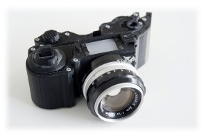
Finally, we have [LeoM’s] OpenReflex rework. OpenReflex is an open source 3D printed Single Lens Reflex (SLR) 35mm film camera. Ok, not every part is 3D printed. You still need a lens, a ground glass screen, and some other assorted parts. OpenReflex avoids the use of a pentaprism by utilizing a top screen, similar to many classic twin lens reflex cameras. OpenReflex is pretty good now, but [Leo] is working to make it easier to build and use. We may just have to break out those rolls of Kodachrome we’ve been saving for a sunny day.

That’s it for this week’s Hacklet! Until next week keep that film rolling and those solid state image sensors acquiring. We’ll keep bringing you the best of Hackaday.io!

sketch of f117 fighter flying

Ask Hackaday: How Did They Shoot Down A Stealth Aircraft?

It was supposed to be a routine mission for U.S. Air Force Lt. Col. Darrell P. Zelko, a veteran pilot of the 1991 Gulf War. The weather over the capital city of Serbia was stormy on the night of March 27th, 1999, and only a few NATO planes were in the sky to enforce Operation Allied Force. Zelco was to drop 2 laser guided munitions and get back to his base in Italy.

There was no way for him to know that at exactly 8:15pm local time, a young Colonel of the Army of Yugoslavia had done what was thought to be impossible. His men had seen Zelco’s unseeable F117 Stealth Fighter.

Seconds later, a barrage of Soviet 60’s era S-125 surface-to-air missiles were screaming toward him at three times the speed of sound. One hit. Colonel Zelco was forced to eject while his advanced stealth aircraft fell to the ground in a ball of fire. It was the first and only time an F117 had been shot down. He would be rescued a few hours later.

How did they do it? How could a relatively unsophisticated army using outdated soviet technology take down one of the most advanced war planes in the world? A plane that was supposed be invisible to enemy radar? As you can imagine, there are several theories. We’re going deep with the “what-ifs” on this one so join us after the break as we break down and explore them in detail.

Continue reading “Ask Hackaday: How Did They Shoot Down A Stealth Aircraft?”

Retrotechtacular: The Voder From Bell Labs

This is the under-the-hood view of the keyboard for the Voder (Voice Operating Demonstrator), the first electronic device capable of generating continuous human speech. It accomplishes this feat through a series of keys that generate the syllables, plosives, and affricatives normally produced by the human larynx and shaped by the throat and tongue. This week’s film is a picture montage paired with the audio from the demonstration of the Voder at the 1939 World’s Fair.

The Voder was created by one [Homer Dudley] at Bell Laboratories. He did so in conjunction with the Vocoder, which analyzes human-generated speech for encrypted transfer and re-synthesizes it on the other end. [Dudley] spent over 40 years researching speech at Bell Laboratories. His development of both the Voder and the Vocoder were instrumental in the SIGSALY project which aimed to deliver encrypted voice communication to the theatres of WWII.

Continue reading “Retrotechtacular: The Voder From Bell Labs”

Thumbnail that say The Hacklet

Hacklet #10 Cryptography And Reverse Engineering

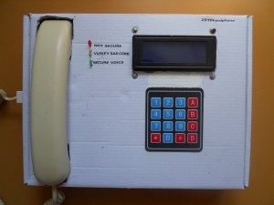
10 In honor of DEFCON, this week we’re looking at some cryptography and reverse engineering projects over at Hackaday.io hardware reverse engineeringEvery hacker loves a hardware puzzle, and [Tom] has created a tool to make those puzzles. His Hardware Reverse Engineering Learning Platform consists of a shield with two ATmega328 chips and an I2C EEPROM. The two Atmel chips share a data bus and I2C lines. Right in the middle of all this is an ST Morpho connector, which allows an ST Nucleo board to act as a sniffer. The platform allows anyone to create a reverse engineering challenge! To successfully reversechip whisper engineer a board, it sure helps to have good tools. [coflynn] is giving that to us in spaces with The ChipWhisperer. ChipWhisperer is an open source security research platform. The heart of the system is a Xilinx Spartan 6 FPGA. The FPGA allows very high speed operations for things like VCC and clock glitching. ChipWhisperer is an entire ecosystem of boards – from LNA blocks to field probes. The entire system is controlled from an easy to use GUI. The end result is a powerful tool for hardware attacks. nsa-awayOn the Encryption side of the house, we start by keeping the Feds at bay. The [Sector67] hackerspace has collectively created NSA AWAY. NSA AWAY is a simple method of sending secure messages over an insecure medium – such as email. A one-time use pad is stored on two SD cards, which are used by two Android devices. The message sender uses an Android device to encrypt the message. On the receive side, the message can be decoded simply by pointing an android device’s camera at the encrypted data. So easy, even a grandparent could do it! buryitNext up is [Josh’s] Bury it under the noise floor. “Bury it” is an education for cryptography in general, and steganographic software in particular. [Josh] explains how to use AES-256 encryption, password hashing, and other common techniques. He then introduces steganography  by showing how to hide an encrypted message inside an image. Anyone who participated in Hackaday’s ARG build up to The Hackaday Prize will recognize this technique. zrtphardphone[yago] gives us encrypted voice communications with his ZRTP Hardphone. The hardphone implements the ZRTP, a protocol for encrypted voice over IP communications. The protocol is implemented by a Raspberry Pi using a couple of USB sound cards. User interface is a 16×2 Line character LCD, a membrane keypad, and of course a phone handset. Don’t forget that you need to build two units,or  whoever you’re trying to call will  be rather confused! moolti-3

Finally we have the Mooltipass. Developed right here on Hackaday by [Mathieu Stephan] and the community at large, Mooltipass is a secure password storage system. All your passwords can be stored fully AES-256 encrypted, with a Smart Card key. Under the hood, Mooltipass uses an Arduino compatible ATmega32U4 microcontroller. UI is through a OLED screen and touch controls.     That’s it for this week! Be sure to check out next week’s Hacklet, when we bring you more of the best from Hackaday.io!

Retrotechtacular: We Heard You Like Tubes, So Here’s A Film About Tube Tubes From The Webtubes

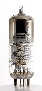
EF80

This lovely little number is the EF80 pentode thermionic valve, or vacuum tube, made by Mullard beginning in 1950. They were used in radio and radar applications, but most of them wound up in VHF television sets. This week’s Retrotechtacular takes a close look at the assembly of and on-site materials production for the EF80 in particular.

The film begins with slow and careful hand assembly of an EF80. The cathode is inserted into a mica disc, and a series of three grids are placed over the cathode. The semicircular anode sits around the outermost grid. Another mica disc is placed on top which does triple duty as a spacer, a base for the getter/plate assembly, and a firewall against the getter flash.The dark lining of the upper part of the tube is the residue of the vaporized getter, which is heated after the first stage of air removal.

Before the vacuuming begins, the inner assembly is mounted on a glass base with nine pins that have been pre-bent to meet the inner assembly wires. The heater, dissipating shield, and a meshy cylinder are added, and then the getter on its plate. A tube is slipped over the assembly and fused to the base in a jig, forming an airtight seal. Continue reading “Retrotechtacular: We Heard You Like Tubes, So Here’s A Film About Tube Tubes From The Webtubes”