Unless your car is fresh off the lot, you’ve probably had the experience of riding in a newer car and seeing some feature or function that triggered a little pang of jealousy. It probably wasn’t enough for you to run out and sign yourself up for a new car loan (which is what the manufacturer was hoping for), but it was definitely something you wished your older model vehicle had. But why get jealous when you can get even?
 [Saabman] wished his 1999 Saab 9-5 had the feature where a quick tap of the turn signal lever would trigger three blinks of the indicator. Realizing this was an electronic issue, he came up with a way to retrofit this function into his Saab by adding an Arduino Pro Micro to the vehicle’s DICE module.
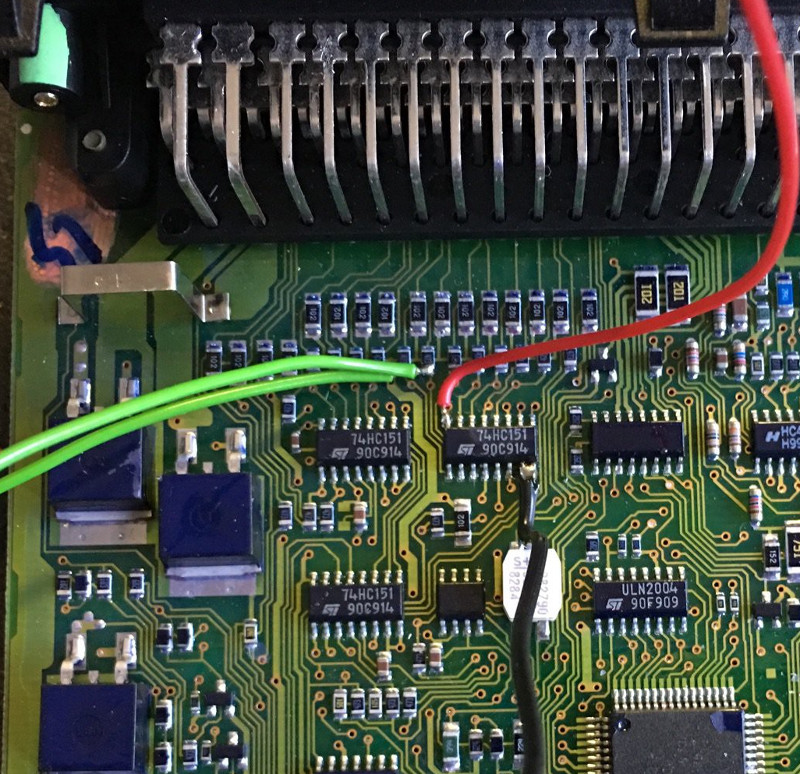
The DICE (which stands for Dashboard Integrated Central Electronics) module controls many of the accessories in the vehicle, such as the lighting and wipers. In the case of the blinkers, it reads the state of the signal lever switches and turns the blinkers on and off as necessary. After poking around the DICE board, [Saabman] found that the 74HC151 multiplexer chip he was after: the state of the blinker switches could be read from pins 1 and 2, and he’d even be able to pull 5 V for the Arduino off of pin 16.
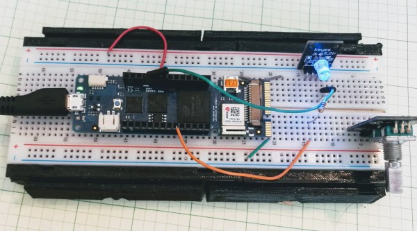
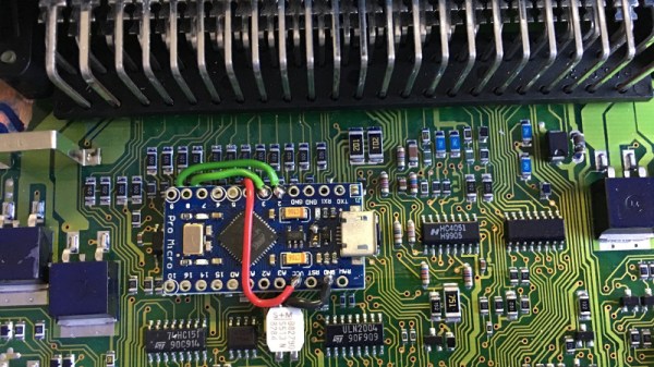
After prototyping the circuit on a breadboard, [Saabman] attached the Pro Micro to the top of the 74HC151 with some double sided tape and got to work on refining the software side of the project. The Arduino reads the state of the turn signal switches, and if they flick on momentarily it changes the pin from an input to an output and brings it high for three seconds. This makes the DICE module believe the driver is holding the turn lever, and will keep the blinkers going. A very elegant and unobtrusive way of solving the problem.
Hackers aren’t complete strangers to the garage; from printing hard to find parts to grafting in their favorite features from other car manufacturers, this slick Saab modification is in good company.