Do jumper wires pulling out of your Uno have you pulling your hair out? Is troubleshooting loose jumpers making you lose your mind? Are your projects backing up because of all the time you’ve lost keeping jumper wires secure in your Arduino Uno? Then you need the all new Ardunio Strain Relief Enclosure!
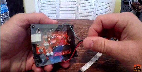
[Jeremy Cook] has had it with loose jumpers pulling out of his Uno, so he designed a case that not only secures the Arduino; it also keeps those dastardly jumper wires from pulling out at the most inconvenient times.
Composed of 3/4 inch thick MDF and 1/8 inch thick polycarbonate, the Arduino Strain Relief enclosure is sure to be a hit for every hacker’s work bench. [Jeremy] used a CNC router to cut the enclosure and top. The plastic top is secured to the MDF base via four 4-40 screws. Interestingly – he applied super glue to the screw holes in the MDF before tapping them. We’ll have to try this trick on our next project!



 [Fandonov] has created