Non-Arduino Powered By A Piece Of Computing History

Sometimes it is a blessing to have some spare time on your hands, specially if you are a hacker with lots of ideas and skill to bring them to life. [Matt] was lucky enough to have all of that and recently completed an ambitious project 8 months in the making – a Non-Arduino powered by the giant of computing history – Intel’s 8086 processor. Luckily, [Matt] provides a link to describe what Non-Arduino actually means; it’s a board that is shield-compatible, but not Arduino IDE compatible.

He was driven by a desire to build a single board computer in the old style, specifically, one with a traditional local bus. In the early days, a System Development Kit for Intel’s emerging range of  microprocessors would have involved a fair bit of discrete hardware, and software tools which were not all too easy to use.

Back in his den, [Matt] was grappling with his own set of challenges. The 8086 is a microprocessor, not a microcontroller like the AVR, so the software side of things are quite different. He quickly found himself locking horns with complex concepts such as assembly bootstrapping routines, linker scripts, code relocation, memory maps, vectors and so on. The hardware side of things was also difficult. But his goal was learning so he did not take any short cuts along the way.

[Matt] documented his project in detail, listing out the various microprocessors that run on his 8OD board, describing the software that makes it all run, linking to the schematics and source code. There’s also an interesting section on running Soviet era (USSR) microprocessor clones on the 8OD. He is still contemplating if it is worthwhile building this board in quantities, considering it uses some not so easy to source parts. If you are interested in contributing to the project, you could get lucky. [Matt] has a few spares of the prototypes which he is willing to loan out to anyone who can can convince him that they could add some value to the project.

Continue reading “Non-Arduino Powered By A Piece Of Computing History”

remote circuit board

Ultimate Remote Is Ultimate

[Joedefa] had a Griffin Beacon Universal Remote that was collecting dust, and decided that it needed to stop collecting dust. He had a growing number of wireless devices in his house and found himself in need of a remote to control them all. The Griffin Beacon fit the bill, but most of his lights and outlets were RF controlled. So he did what hackers do best… broke out the screw driver and soldering iron and rewired it!

[Joedefa] is using an Attiny85 as the brains between an infrared LED and a RF transmit module (if anyone can identify the source of this module, please let everyone know in the comments).  A pair of red and green LEDs lets him know if the remote has received commands successfully.

It’s always nice to see a discontinued product made useful once more with a little ingenuity and an Arduino some hacking skill. Hat’s off to [Joedefa] for a righteous hack!

The Annoying Machine

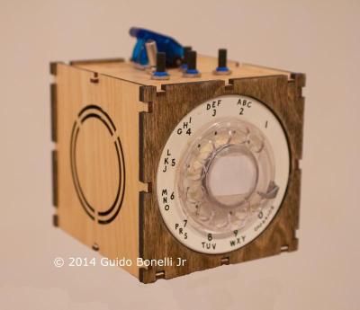
The Useless Machine – a machine with a toggle switch, a mechanical arm, and something that only exists to turn itself off – is a staple of Instructables and builds from random workbenches the world over. It’s cliché, and now hackaday.io has a better project: The Annoying Machine, a machine that exists purely to annoy.

According to [unigamer], the Annoying Machine is the evil cousin of the Useless Machine. On the outside, it’s extremely simple: a switch labeled ‘on’ and ‘off’, and a hole for an LED. Turn the switch on, and the Annoying Machine will emit an annoying buzzing sound. Switch the Machine off, and the buzzing will go away. Then the switch will flick itself back to on. Insidious.

A switch and buzzer is easy enough, but the key component of this build is an actuated rocker switch. It’s basically a normal toggle switch with two additional terminals for a coil that can move the switch back and forth electronically. Throw in an Arduino, buzzer, battery, and a boost converter for the switch, and that’s just about all there is to it.

How to deactivate the Annoying Machine? There’s an accelerometer attached to the Arduino, and by throwing the box up in the air after flicking the switch off, it will reset. There are already plans for a Version 2 of the Annoying Machine that will be even louder and made out of aluminum. Anything to protect it from the inevitable hammers of frustration.

Video below.

Continue reading “The Annoying Machine”

Bill’s Arduino

Pokemon is a great game by itself, but when you realize that not all of the ‘mon are available in one game, trading is required for completion, and some pokemon aren’t available without either hacking or going to a Toys ‘R Us in 1997, you start to see how insidious this game can be. Figuring he could finally complete the game with an Arduino, [Pepijn] decided to build a pokemon storage system.

This build was inspired by an earlier post that also spoofed trades. Instead of building this project around a high-power micro, [Pepijn] decided to use an Arduino. The protocol Game Boys use to communicate with each other is extremely well documented, although that’s only half the battle. Each game using the link cable used specialized data structures for transfer, and after grepping through a disassembled Pokemon ROM,  [Pepijn] figured out how everything worked.

The completed hardware keeps one Pokemon in the EEPROM of an Arduino. It’s not very fast if you want to catch all 151 Pokemon in the Gen 1 games, but any way you look at it, you’re going to be catching a lot of Magikarp anyway.

Converting Morse Code To Text With Arduino

Morse code used to be widely used around the globe. Before voice transmissions were possible over radio, Morse code was all the rage. Nowadays, it’s been replaced with more sophisticated technologies that allow us to transmit voice, or data much faster and more efficiently. You don’t even need to know Morse code to get an amateur radio license any more. That doesn’t mean that Morse code is dead, though. There are still plenty of hobbyists out there practicing for the fun of it.

[Dan] decided to take a shortcut and use some modern technology to make it easier to translate Morse code back into readable text. His project log is a good example of the natural progression we all make when we are learning something new. He started out with an Arduino and a simple microphone. He wrote a basic sketch to read the input from the microphone and output the perceived volume over a Serial monitor as a series of asterisks. The more asterisks, the louder the signal. He calibrated the system so that a quiet room would read zero.

He found that while this worked, the Arduino was so fast that it detected very short pulses that the human ear could not detect. This would throw off his readings and needed to be smoothed out. If you are familiar with button debouncing then you get the idea. He ended up just averaging a few samples at a time, which worked out nicely.

The next iteration of the software added the ability to detect each legitimate beep from the Morse code signal. He cleared away anything too short. The result was a series of long and short chains of asterisks, representing long or short beeps. The third iteration translated these chains into dots and dashes. This version could also detect longer pauses between words to make things more readable.

Finally, [Dan] added a sort of lookup table to translate the dots and dashes back into ASCII characters. Now he can rest easy while the Arduino does all of the hard work. If you’re wondering why anyone would want to learn Morse code these days, it’s still a very simple way for humans to communicate long distances without the aid of a computer.

VendingTweets

A Tweeting Vending Machine

[Sigurd] manage to obtain an old vending machine from his dorm. The only problem was that the micocontroller on the main board was broken. He and his friend decided they could most likely get the machine back into working order, but they also knew they could probably give it a few upgrades.

This system uses two Arduino Pro Minis and an Electric Imp to cram in all of the new features. One Arduino is connected to the machine’s original main board. The Arduino interfaces with some of the shift registers, relays, and voltage regulators. This microcontroller also lights up the buttons on the machine as long as that particular beverage is not empty. It controls the seven segment LED display, as well as reading the coin validator.

The team had to reverse engineer the original coin validator in order to figure out how the machine detected and counted the coins. Once they figured out how to read the state of the coins, they also built a custom driver board to drive the solenoids.

A second Arduino is used to read NFC and RFID cards using a Mifare RC522 reader. The system uses its own credit system, so a user can be issued a card with a certain amount of pre-paid credit. It will then deduct credit appropriately once a beverage is vended. The two Arduinos communicate via Serial.

The team also wanted this machine to have the ability to communicate with the outside world. In this case, that meant sending cheeky tweets. They originally used a Raspberry Pi for this, but found that the SD card kept getting corrupted. They eventually switched to an Electric Imp, which worked well. The Arduino sends a status update to the Imp every minute. If the status changes, for example if a beverage was dispensed, then the Imp will send a tweet to let the world know. It will also send a tweet to the maintenance person if there is a jam or if a particular slot becomes empty. Continue reading “A Tweeting Vending Machine”

Altoids Tin Network Analyzer

Network Analyzers are frequently used for measuring filters, making them extremely valuable for building radios and general mucking about with RF. They are, however, extremely expensive. You can, however, build one in an Altoids tin with an Arduino Nano, a small screen, and an AD9850 frequency synthesis module picked up on eBay.

The basic idea behind a network analyzer is to feed a frequency into a device, and measure the amplitude coming out of the device, and plot this relationship over a frequency. [Bill Meara] has been a human network analyzer before, changing frequencies and plotting the output of devices under test by hand. [DuWayne] (KV4QB) build a device to automate the entire process.

The block diagram is easy enough – an AD9850 sends a signal to the device, and this is measured by the Arduino with a small amplifier. The signal is measured again when it comes back from the device under test, and all this is plotted on a small display. Simple, and [DuWayne] is getting some very good readings with a lowpass filter and crystal filter made on a small solderless breadboard.