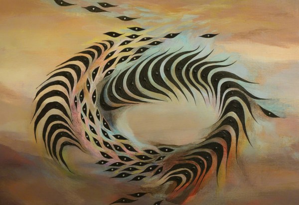
Using The Second Microcontroller On An Arduino

While newer Arduinos and Arduino compatibles (including the Hackaday.io Trinket Pro. Superliminal Advertising!) either have a chip capable of USB or rely on a V-USB implementation, the old fogies of the Arduino world, the Uno and Mega, actually have two chips. An ATMega16u2 takes care of the USB connection, while the standard ‘328 or ‘2560 takes care of all ~duino tasks. Wouldn’t it be great is you could also use the ’16u2 on the Uno or Mega for some additional functionality to your Arduino sketch? That’s now a reality. [Nico] has been working on the HoodLoader2 for a while now, and the current version give you the option of reprogramming the ’16u2 with custom sketches, and use seven I/O pins on this previously overlooked chip.

Unlike the previous HoodLoader, this version is a real bootloader for the ’16u2 that replaces the DFU bootloader with a CDC bootloader and USB serial function. This allows for new USB functions like HID keyboard, mouse, media keys, and a gamepad, the addition of extra sensors or LEDs, and anything else you can do with a normal ‘duino.

Setup is simple enough, only requiring a connection between the ‘328 ISP header and the pins on the ’16u2 header. There are already a few samples of what this new firmware for the ’16u2 can do over on [Nico]’s blog, but we’ll expect the number of example projects using this new bootloader to explode over the coming months. If you’re ever in an Arduino Demoscene contest with an Arduino and you’re looking for more pins and code space, now you know where to look.

ArTICam Interfaces Game Boy Camera With TI Calculators

[Christopher Mitchell] has given Texas Instruments calculators the ability to capture images through a Game Boy Camera with ArTICam. First introduced in 1998, The Game Boy Camera was one of the first low-cost digital cameras available to consumers. Since then it has found its way into quite a few projects, including this early Atmel AT90 based hack, and this Morse code transceiver.

TI calculators don’t include a Game Boy cartridge slot, so [Christopher] used an Arduino Uno to interface the two. He built upon the Arduino-TI Calculator Linking (ArTICL) Library  to create ArTICam. Getting the Arduino to talk with the Game Boy Camera’s M64282FP image sensor turned out to be easy, as there already are code examples available. The interface between the camera sensor and the Arduino is simple enough. 6 digital lines for an oddball serial interface, one analog sense line, power and ground. [Christopher] used a shield to solder everything up, but says you can easily get away with wiring directly the Arduino Uno’s I/O pins. The system is compatible with the TI-83 Plus and TI-84 Plus family of calculators. Grabbing an image is as simple as calling  GetCalc(Pic1) from your calculator program.

So, If you have an old calculator lying around, give it a try to enjoy some 128×123-pixel grayscale goodness!

Ray Tracing On An Arduino

[Greg] implemented a simple ray tracer for Arduino as a fun exercise and a way to benchmark the processor. He started out with the Moller-Trumbore algorithm, a common ray-tracing algorithm that calculates the intersection of a ray with a triangular plane without doing any pre-calculation of the planes. His code supports one static light and one static camera, which is enough to render a simple scene.

[Greg] started out with a small scene composed of a few polygons, but just finished up a scene with 505 vertices, 901 faces, and reflective surfaces (shown above). He made the above render on his PC emulator, but estimates that it would take just over 4 days to render on the Arduino. [Greg]’s project supports multiple bounces of light, which differentiates his ray tracer from some we’ve covered before (and which explains why it takes so long to render).

The ray tracer is implemented entirely with double-precision floats. This translates to a ton of software float emulation instructions, since the Arduino doesn’t have a floating-point unit. While this ray tracer can’t render anything near real-time graphics due to the slowness of the microcontroller, it’s still a great proof of concept.

The title image for this post was rendered on a modern PC, taking 263 seconds to complete. The same scene, at 64×64 resolution, was rendered on the Arduino, taking 4008 seconds to complete. That render is below.

ardu

Enhanced Coffee Brewer Knows How Much Of A Caffeine Addict You Are

Who should chip in the most to restock the community coffee supply at work is a common point of contention at some offices. This RFID infused coffee brewer called Juraduino by [Oliver Krohn] solves the issue at his workplace once and for all by logging how much is being consumed by each person and how often; quite the diplomatic hack.

[Oliver] donated his old Jura Coffee maker to his office with some added hardware cleverly hidden underneath the faceplate of the machine. An Arduino mounted within runs the show, powered through mini USB from the logic unit of the coffee maker itself. Once a co-worker swipes their RFID card over the front of the machine, a real-time clock module stamps when the coffee was requested, and then logs the amount selected by that person on a mini SD card. The data stored is sent via an additional bluetooth module to a custom app [Oliver] created with MIT App Inventor for his phone which displays the information. These details can then be exported in the form of an email addressed to everyone in the office at the end of the week, announcing definitively who can be counted on to restock the bulk of the community supplies.

Though there isn’t a link available with further documentation, [Oliver] mentions in the ‘details’ portion of his video that he’d be happy to share that information with anyone who contacts him regarding the project. You can see the Jura at work below:

Continue reading “Enhanced Coffee Brewer Knows How Much Of A Caffeine Addict You Are”

IcosaLEDron: A 20-Sided Light Up Ball

Tired of balls that are just balls, and not glowing geometric constructions of electronics and wonderment? Get yourself an IcosaLEDron, the latest in Platonic solids loaded up with RGB LEDs.

The folks at Afrit Labs wanted a fun, glowy device that would show off the capabilities of IMUs and MEMS accelerometers. They came up with a ball with a circuit board inside and twenty WS2812B RGB LEDs studded around its circumference

The frame of the ball is simply a set of twenty tessellated triangles that can be folded up during assembly. The outer shell of the ball is again printed in one piece, but fabricated out of transparent NinjaFlex, an extraordinarily odd, squishy, and likely indestructible material.

Inside the IcosaLEDron is a PCB loaded up with an ATMega328p, an accelerometer, a LiPo battery charger, and quite a bit of wiring. Once the ball is assembled and locked down, the squishy outer exterior is installed and turned into a throwable plaything.

If 20 sides and 20 LEDs aren’t enough, how about a an astonishing 386-LED ball that’s animated and knows its orientation? That’s a project from Null Space Labs, and looking at it in person is hypnotic.

via Makezine

Solving Arduino’s Stk500_getsync() Error

[psgarcha] took a year-old Arduino Uno on an international trip and upon returning found something was wrong. Every time he would try to upload, he would get the dreaded avrdude error, ‘stk500_getsync(): not in sync resp=0x00’. The Rx light would blink a few times during the attempted upload, but the tx light did not. Somehow, something was terribly wrong with the ‘duino, and [psgarcha] dug deep to figure out why.

To test the quality of the Arduino’s serial connection, [psgarcha] performed a loopback test; basically a wire plugged into the Tx and Rx pins of the Arduino. Sending a short message through the serial port showed the problem wasn’t the USB cable, the ATmega16u2 on the ‘duino, or any traces on the board. This would require more thought.

The main reason for the error would then be no communication between the computer and the ‘duino, the wrong COM port selected, the wrong board selected in the Arduino text editor, or timing errors or a corrupt bootloader. The first three errors were now out of the question, leaving timing errors and a corrupt bootloader. Troubleshooting then moved on to ordering a new programmer, and still this didn’t work with the broken Uno.

Frustrated with one of the greatest failures to become an Arduino tinkerer, [psgarcha] took a good, long look at the Uno board. He glanced over to an Arduino Mega board. Something looked different. On the Uno, the resonator had blown off. Problem found, at least.

Replacing the blown part with a hilariously large can crystal oscillator, [psgarcha] was back in business. This isn’t how you would fix 99% of getsync() errors, and it’s difficult imagining a situation where a this part would randomly blow, but if you’re ever looking at a nearly intractable problem, you need to start looking at what really shouldn’t fail.

Resonator my fix (1)

Awesome rework, though.


A Modern Woodworking Workbench

This is a post about workbenches, but not the benches you’re probably thinking about. Workbenches meant for electronics development are simple matters – just about any flat surface, a few shelves for equipment, and an anti-static mat will be fine for every conceivable use.  Workbenches for woodworking are a separate matter entirely. There’s actually quite a bit of history behind the development of the woodworking workbench, but the basic idea is a thick laminated wood top, integrated vices, holes in the work surface for bench dogs, and ergonomics that allow for comfortable use of hand tools. The basic design of these benches hasn’t changed much in several hundred years, and [Dirk] thought the design was ready for a modern update.

Continue reading “A Modern Woodworking Workbench”