If you carry a cell phone with GPS, you always know where you are on the planet. But what about inside buildings or even your own home? Knowing if you’re in the kitchen or the living room would be a great feature for home automation systems. Lights could come on as you enter the room and your music could follow you on the home audio system. This is exactly the what [Eric] is working on with his Radiolocation using a Pocket Size Transceiver project. [Eric] started this project as an entry in the Trinket Everyday Carry Contest. He didn’t make the top 3, but was one of the fierce competitors who made the competition very hard to judge!
The heart of the project is determining Time Of Flight (TOF) for a radio signal. Since radio waves move at the speed of light, this is no small feat for an Arduino based design! [Eric] isn’t re-inventing the wheel though – he’s basing his design on several research papers, which he’s linked to his project description. Time of flight calculations get easier to handle when calculating round trip times rather than one way. To handle this, one or more base stations send out pings, which are received and returned by small transponders worn by a user. By averaging over many round trip transmissions, a distance estimation can be calculated.
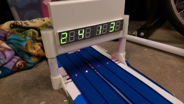
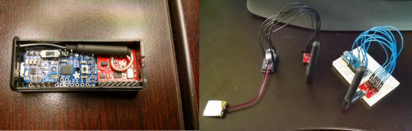
[Eric] used a Pro Trinket as his mobile transponder, while an Arduino Micro with it’s 16 bit counter acted as the base station. For RF, he used the popular Nordic nRF24L01+ 2.4 GHz transceiver modules. Even with this simple hardware, he’s achieved great results. So far he can display distance between base and transponder on a graph. Not bad for a DIY transponder so small if fits in a 2xAAA battery case! [Eric’s] next task is working through multipath issues, and testing out multiple base stations.
Click past the break to see [Eric’s] project in action!
Continue reading “Trinket Uses RF To Track You Through The House”