Measuring the usage of domestic utilities such as water, gas or electricity usually boils down to measuring a repetitive pulse signal with respect to time. To make things easy, most modern utility meters have a pulsed LED output, which can be used to monitor the consumption by using an external optical sensor. But what do you do if your meter isn’t so cooperative?
That’s exactly what [Francesco] had to figure out while developing the non-invasive gas tracking system he calls ESPmeter. His meter might not have an LED, but it did have a magnet attached to the counter disk which activated an internal hall sensor. With some hacking, he was able to attach an external Hall-effect sensor to pick up this magnet and use the signal to monitor his daily gas consumption.
A big stumbling block in such projects is the issue of powering the device for an extended period, and remembering when it’s time to change the batteries. With the clever use of commonly available parts, he was able to reduce power consumption allowing three AA batteries to last about a year between changes. For one thing, he uses an ATtiny13 to actually read the sensor values. The chip doesn’t run continuously, its watchdog is set at 1 Hz, ensuring that the device is woken up often enough so that it has time to power up the sensor and detect the presence of the magnet. Battery voltage is also measured via a voltage divider connected to the chip’s ADC pin.
At regular intervals throughout the day, the ESP8266 polls the ATtiny13 to pull the stored sensor pulses and voltage measurement. Then at midnight, the ESP transmits all the collected data to a remote server. Overall, this whole scheme allows [Francesco] to reliably gather his gas consumption data while not having to worry about batteries until he gets the low voltage notification. Since the data visualization requirements are pretty basic, he is keeping things simple by using Plotly to display his time series data.
If you are unfortunate enough to have an even older meter which doesn’t use optical or magnetic rotation sensing, you can use a disassembled mouse to keep track of the Gas Meter.
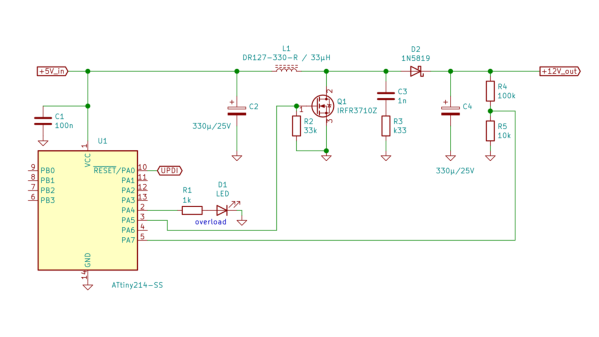
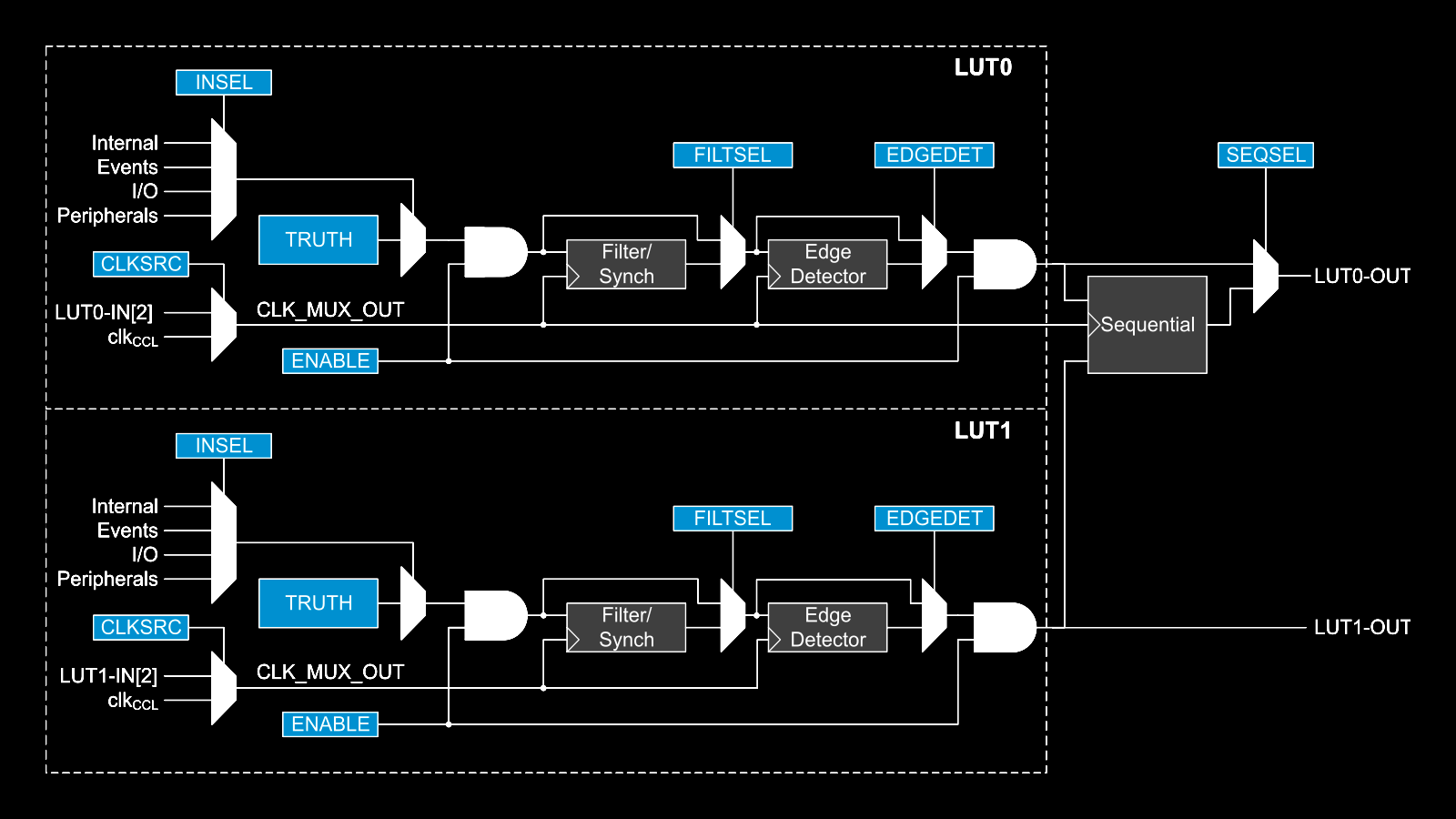
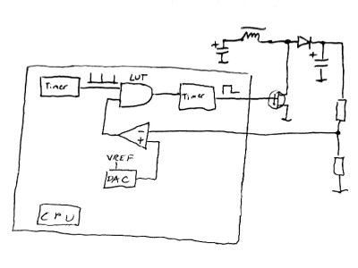 This napkinCAD sketch shows how [SM6VFZ] implemented the boost regulator in the ATtiny214. The AND gate is formed using one of the CCL LUT’s. The first “timer 1” on the left, connected to one input of the AND gate, is free running and set at 33 kHz. The analog comparator compares the boosted output voltage against an internally generated reference voltage derived from the DAC. The output of the comparator then “gates” timer 1 signal to trigger the second “timer 2” — which is a mono-shot timer set to max out at 15 us. This makes sure there is enough time left for the inductor to completely release its energy before the next cycle starts. You can check out the code that [SM6VFZ] used to built this prototype, and his generous amounts of commenting makes it easy to figure out how it works.