The aptly named [Clickity Clack]’s new YouTube channel promises to be very interesting if he can actually pull off a working computer using nothing but relays. But even if he doesn’t get beyond the three videos in the playlist already, the channel is definitely worth checking out. We’ve never seen a simpler, clearer explanation of binary logic, and [Clickity Clack]’s relay version of the basic logic gates is a great introduction to the concepts.
Using custom PCBs hosting banks of DPDT relays, he progresses from the basic AND and XOR gates to half adders and full adders, explaining how carry in and carry out works. Everything is modular, so four of his 4-bit adder cards eventually get together to form a 16-bit adder, which we assume will be used to build out a very noisy yet entertaining ALU. We’re looking forward to that and relay implementations of the flip-flops and other elements he’ll need for a full computer.
And pay no mind to our earlier dismissal of non-traditional computer projects. It’s worth checking out this discrete 7400 logic computer and this all-transistor build. They’re impressive too in their own way, if a bit quieter than [Clickety Clack]’s project.
What I particularly like about the Van de Graaff (or VDG) is that it’s a combination of a few discrete scientific principles and some mechanically produced current, making it an interesting study. For example, did you know that its voltage is limited mostly by the diameter and curvature of the dome? That’s why a handheld one is harmless but you want to avoid getting zapped by one with a 15″ diameter dome. What follows is a journey through the workings of this interesting high voltage generator.
Wherever you may live in the world, who do you wish to smile upon you and deliver good fortune? You may be surprised to discover that for a significant number of Brits this role is taken by someone called [Ernie].
What, [Jim Henson]’s Ernie from Sesame Street‘s famous duo Bert and Ernie? Sadly not, because the owner of a [Rubber Duckie] can’t offer you the chance of a million quid every month. Instead, [Ernie] is a computer that has been anthropomorphised in the national imagination. More properly referred to as E.R.N.I.E, for Electronic Random Number Indicator Equipment, he is the machine that picks the winning bond numbers for the Premium Bonds, a lottery investment scheme run by the British Government.
Brits have been able to buy £1 bonds, up to 50,000 of them today, since the 1950s, and every month they are entered into a drawing from which ERNIE picks the winners. The top two prizes are a million pounds, but for most bond holders the best they can hope for is the occasional £25 cheque. Premium Bonds are often bought for young children so a lot of Brits will have a few, often completely forgotten. Prizes never expire, so if you are the holder of old bonds you should consider asking National Savings and Investments whether anything is owed to you.
The Great Grandfather of Premium Bond Drawings
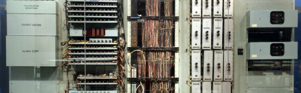
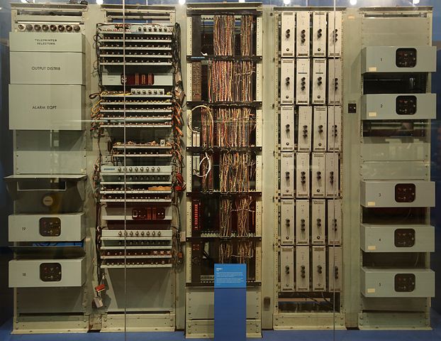
The original 1957 ERNIE, now in the collection of the Science Museum, London. Geni [CC BY-SA 4.0-3.0-2.5-2.0-1.0, via Wikimedia Commons.The current ERNIE is the fourth-generation model, but our attention today is on its 1950s ancestor. In a way it’s the most interesting of the machines because it has an unusual pedigree, being a creation of the Post Office Research Station, at Dollis Hill, London. As such it came from the lab of the Colossus engineer [Tommy Flowers], and is described as being a descendant of the now-famous but then still top-secret first digital computer used by the World War Two codebreakers. It’s thus a fascinating study for the student of computer history as well as for its role in British postwar social history, because it represents the only glimpse (had they known it at the time) that the British public had of the technology that had helped them so much a decade earlier.
A significant effort was made to ensure that the draw was truly random, and the solution employed by [Flowers] and his team was thoroughly tested before each draw. The thermionic noise generated across a neon tube was sampled, and this random voltage delivered the truly random numbers used to generate the winning bond numbers. The machine’s construction is extremely reminiscent of its wartime predecessor, however it is as well to bear in mind that it owes this to the standard racking and paint used in British telephone exchanges of the day. Gone though are the octal tubes, and in their place are their more familiar miniature successors.
We have two films for you showing this incarnation of ERNIE in action. The first is a National Savings promotional film which explains ERNIE’s purpose, while the second shows us the Minister of the time starting the first draw. Believe it or not, this was a cause of major national excitement at the time.
As a hacker, chances are that you have built a homopolar motor, as you only need three things: a battery, a magnet and some copper wire. There are zillions of videos on YouTube. This time we want to show you [Electric Experiments Roobert33]´s version. Definitely a fresh twist on the ubiquitous design that you see everywhere. His design is a bit more complicated, but the result makes the effort worthwhile.
Right hand rule for the Lorenz force. By Jfmelero, via Wikimedia Commons
The homopolar motor was the first electric motor ever built. Created Michael Faraday in 1821, it works because of the Lorentz force. This force acts on any current-carrying conductor that is immersed in a magnetic field which is perpendicular to the current. These motors really have no practical applications, but are an excellent way to learn basic aspects of electromagnetism.
In this setup, there are two conductive rings placed above a wooden base, connected to the battery terminals. Neodymium magnets are connected by a conductive rod that pivots in the center of the rings, closing the circuit and allowing the flow of current. Then the Lorentz force makes its magic and pushes the rod and magnets in a circular motion.
Very clean and well-edited work, as are other videos by [Electric Experiments Roobert33]. You may want to replicate this nice motor, or you can also make the simpler version to start experimenting.
You’re in a desert, walking along in the sand when all of a sudden you look down and see a tortoise. It’s crawling toward you.
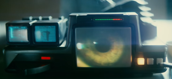
Any Sci-Fi fan knows this is a question from the iconic Voight-Kampff test, as made famous by the movie Blade Runner. Humans pass the test. Replicants fail and are “retired”. We may not have replicants just yet, but [Tom Meehan] is building his own version of the Voight-Kampff machine. He’s entered it in the 2017 Hackaday Sci-Fi Contest.
The machine itself is an odd mix of 70’s and 80’s electronics with older technology. Three mini CRT displays, a sensor arm, and a bellows are some of the machine’s best-known features. [Tom] is starting with the sensor arm, an odd mix of belts and telescoping rods. He’s already got a manually operated prototype built. Add a motor, and one part of the machine is ready for action.
[Tom’s] version of the Voight-Kampff test isn’t going to be a just movie prop. He plans to add a sensor suite which will turn his machine something of a modern polygraph. A Non-contact Temperature sensor will measure blush response. Iris images will be captured by a Raspberry Pi NoIR camera. Pulse oxygen and galvanic skin response will also be captured by a separate hand module. All this data will be processed by a Raspberry Pi computer.
There’s quite a lot of work to be completed. Let’s hope for humanity’s sake that [Tom] gets it done before the contest deadline of March 6.
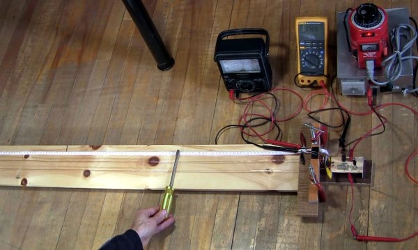
How do you test the oscillator circuit you just made that runs between 200MHz and 380MHz if all you have is a 100MHz oscilloscope, a few multimeters and a DC power supply? One answer is to put away the oscilloscope and use the rest along with a length of wire instead. Form the wire into a Lecher line.
That’s just what I did when I wanted to test my oscillator circuit based around the Mini-Circuits POS-400+ voltage controlled oscillator chip (PDF). I wasn’t going for precision, just verification that the chip works and that my circuit can adjust the frequency. And as you’ll see below, I got a fairly linear graph relating the control voltages to different frequencies.
What follows is a bit about Lecher lines, how I did it, and the results.
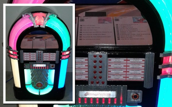
Restoring a genuine vintage jukebox is a fun project, but finding suitable candidates can be a difficult proposition. Not only can a full-size machine take a huge bite out of your wallet, it can take up a lot of room, too. So a replica miniature jukebox might be just the thing.
We have to admit, at first glance [Allan_D_Murray]’s project seemed like just another juke upgrade. It was only after diving into his very detailed build log that we realized this classic-looking juke is only about 30″ (80 cm) tall. It’s not exactly diminutive, but certainly more compact than the original Wurlitzer 1015 from which it draws its inspiration. But it sure looks like the real thing. Everything is custom made, from the round-top case to the 3D-printed trim pieces, which are painted to look like chrome-plated castings. The guts of the juke are pretty much what you’d expect these days — a PC playing MP3s. But an LCD monitor occupies the place where vinyl records would have lived in the original and displays playlists of the albums available. There’s an original-looking control panel on the front, and there are even bubblers in the lighted pilasters and arches.
Hats off to [Allan] for such a detailed and authentic tribute to a mid-century classic. But if a reproduction just won’t cut it for you, check out this full-size juke with the original electronics.