When it comes to the quest for artifacts from the Space Race of the 1960s, few items are more sought after than flown hardware. Oh sure, there have been stories of small samples of the 382 kg of moon rocks and dust that were returned at the cost of something like $25 billion making it into the hands of private collectors, and chunks of the moon may be the ultimate collector’s item, but really, at the end of the day it’s just rock and dust. The serious space junkie wants hardware – the actual pieces of human engineering that helped bring an epic adventure to fruition, and the closer to the moon the artifact got, the more desirable it is.
Sadly, of the 3,000,000 kg launch weight of a Saturn V rocket, only the 5,600 kg command module ever returned to Earth intact. The rest was left along the way, mostly either burned up in the atmosphere or left on the surface of the Moon. While some of these artifacts are recoverable – Jeff Bezos himself devoted a portion of his sizable fortune to salvage one of the 65 F1 engines that were deposited into the Atlantic ocean – those left on the Moon are, for now, unrecoverable, and in most cases they are twisted heaps of wreckage that was intentionally crashed into the lunar surface.
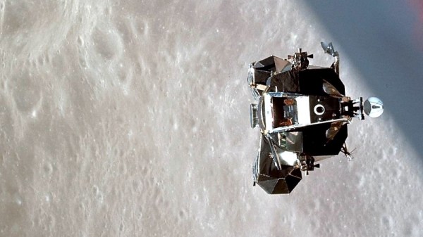
But at least one artifact escaped this ignominious fate, silently orbiting the sun for the last 50 years. This lonely outpost of the space program, the ascent stage from the Apollo 10 Lunar Module, appears to have been located by a team of amateur astronomers, and if indeed the spacecraft, dubbed “Snoopy” by its crew, is still out there, it raises the intriguing possibility of scoring the ultimate Apollo artifact by recovering it and bringing it back home.
Continue reading “Snoopy Come Home: The Search For Apollo 10”