When fate lands a very high quality lens in front of you, what do you do with it? If you are [Tim Hamilton], the solution is obvious. Use it in a huge large-format camera.
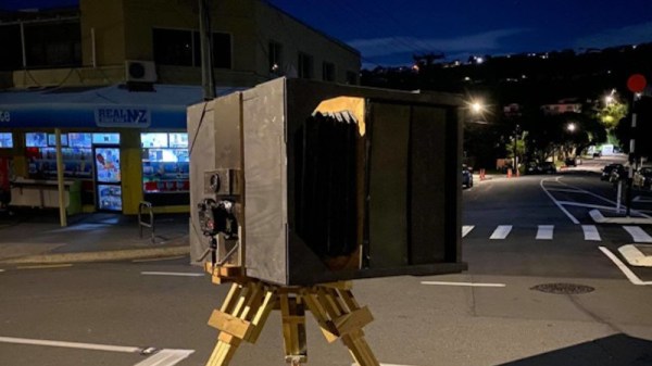
The lens came from a newspaper magnifier made redundant by digitalisation and used as a paperweight. It’s an extremely high quality piece of optical equipment so seeing it wasted in this way was a source of distress. So after characterising it an enormous scaled-up box and bellows was constructed, and set upon a suitably substantial wheeled tripod.
Instead of a huge piece of film or some unobtainable giant electronic sensor, the image is projected onto a large screen at the rear of the camera. A modern digital camera is mounted inside the box just beneath the lens and photographs the screen, resulting in the feel of the largest of large format cameras with the convenience of a digital format. The resulting images have a special quality to them that recalls pictures from the past, and definitely makes the camera a special if slightly inconvenient device.
This may be one of the larger cameras we’ve featured, but it’s not the first that uses a similar technique.