Anyone who was at Supercon will no doubt remember the badges that dangled around everyone’s neck. Some were reasonable, while some were neck-straining monsters that added anything and everything to hack the badge into something cool. We saw everything from AI cameras to a fully autonomous vehicle being worn with pride.
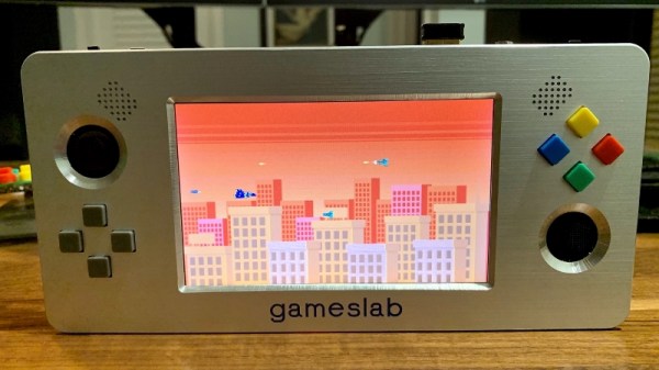
Sadly, one that we missed was Gameslab, [Craig J. Bishop]’s FPGA-based portable game console. No, not that FPGA-based game console; in an example of great minds thinking alike, [Craig] had actually been toying with his own handheld console design for quite some time. And we have to say the results are stunning.
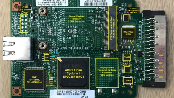
The FPGA at the heart of this is a Xilinx Zynq FPGA-ARM Cortex A9 combo SoC, normally a prohibitively expensive monster of a chip. When [Craig] found “refurbished” Zynq chips on eBay for less than 10% of the cost of new units, it was literally game-on for the build. The console required a six-layer PCB to support the big BGA chip and the hundreds of support components around it. There’s a 5″ TFT touchscreen with a video controller implemented in the FPGA, a stereo sound system, and all the buttons and thumbsticks you’d expect on a modern console.
For our money, the best part is the case, about which [Craig] has yet to share any details. But it looks like a machined aluminum plate with wide chamfers around each cutout that contrast nicely with the brushed surface. We’ll be looking forward to more details on that and on progress with Gameslab.