Hackaday Retro Edition: A New Commodore 64 Case

Some time in the 80s, the plastic injection molds for the Commodore 64C, the Commodore 128, and the Plus/4 were shipped from somewhere in Asia to the great Commodore Mother Brain in West Chester, Pennsylvania. These molds had already produced a million or two cases, but there were some issues with production – too much waste, or something like that. A mechanical engineer took a look at the molds, sent out some recommendations, and moved the 2500 pound molds to a corner of the building.

For some time after a gray day in April, 1994 these molds sat in a West Chester, Pennsylvania warehouse until they were sold off. They made their way to a plastics manufacturer around Dallas, Texas where they sat for twenty years. All things must pass, sometimes several times, and this plastics manufacturer closed down, contacted an auctioneer, and began to sell off some of their equipment.

The hero of our story, [Dallas Moore], owns a small business, buying and selling everything from Barbie dolls to antiques. He found an ad for an auction at a plastics manufacturing plant in the newspaper, and figuring he could find something interesting, headed out to the auction preview.

The auctioneer at this liquidation sale asked [Dallas] what he did, and mentioned there was something pretty cool tucked away in a warehouse full of hardened steel molds. Something about molds for old computers. These were the molds for the Commodore 64C, Commodore 128, and the Commodore Plus/4. A literal crucible of computing history, stacked on a pallet and up for sale.

The auctioneer said one of his friends was interested in the molds, and thought they would make a neat coffee table. Something about this struck [Dallas] the wrong way and for the entire drive home he thought about someone taking history and turning it in to a piece of furniture. He decided to buy these molds and lugged the three 2500 pound pieces of hardened steel to his shop. Not wanting to let a good piece of history go to waste, he contacted another plastics manufacturer, planned a run of a thousand or so Commodore 64C cases in red, white, and blue. [Dallas] is funding the whole production run through Kickstarter.

To me, this is one of the greatest retrocomputing successes in recent memory. There will always be someone putting SD cards in old computers, getting them on the Internet (and especially pointed towards our retro edition), and cloning complete systems in FPGAs. This, though, is a clear example of someone recognizing the historical importance of several thousand pounds of steel, realizing there’s a market out there, and doing the leg work to remanufacture these pieces of history.

I put in my $45 for a red one, and I tipped off [Bil Herd], designer of the C128 and Plus/4, to this Kickstarter. He’s been talking with [Dallas], there I’m sure he’ll chime in on the comments with some retellings of Commodore battle stories.

If it arrives in time, I’ll be bringing my limited-edition red 64C case to the Vintage Computer Festival in Wall, NJ April 17-19. That’s a plug for the event. If you’re in the area, you should come.

EDIT: [Dallas] has a different story of where the molds came from.

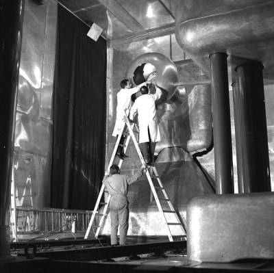
Quantel

Retrotechtacular: The Early Days Of CGI

We all know what Computer-Generated Imagery (CGI) is nowadays. It’s almost impossible to get away from it in any television show or movie. It’s gotten so good, that sometimes it can be difficult to tell the difference between the real world and the computer generated world when they are mixed together on-screen. Of course, it wasn’t always like this. This 1982 clip from BBC’s Tomorrow’s World shows what the wonders of CGI were capable of in a simpler time.

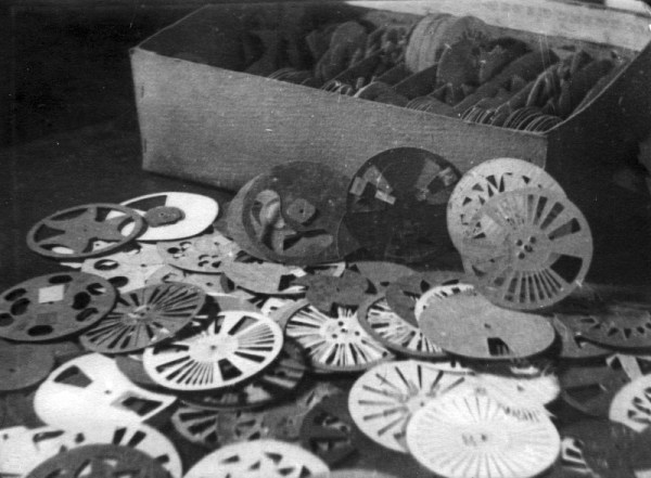
In the earliest days of CGI, digital computers weren’t even really a thing. [John Whitney] was an American animator and is widely considered to be the father of computer animation. In the 1940’s, he and his brother [James] started to experiment with what they called “abstract animation”. They pieced together old analog computers and servos to make their own devices that were capable of controlling the motion of lights and lit objects. While this process may be a far cry from the CGI of today, it is still animation performed by a computer. One of [Whitney’s] best known works is the opening title sequence to [Alfred Hitchcock’s] 1958 film, Vertigo.

Later, in 1973, Westworld become the very first feature film to feature CGI. The film was a science fiction western-thriller about amusement park robots that become evil. The studio wanted footage of the robot’s “computer vision” but they would need an expert to get the job done right. They ultimately hired [John Whitney’s] son, [John Whitney Jr] to lead the project. The process first required color separating each frame of the 70mm film because [John Jr] did not have a color scanner. He then used a computer to digitally modify each image to create what we would now recognize as a “pixelated” effect. The computer processing took approximately eight hours for every ten seconds of footage. Continue reading “Retrotechtacular: The Early Days Of CGI”

Fail Of The Week : Measuring DC Current Has To Be Easy, Right?

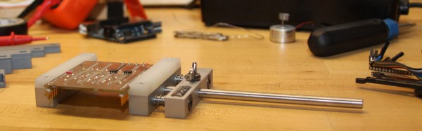
[DainBramage] needed a DC ammeter to check how long his amateur radio station would be able to stay powered on battery backup power. The one’s he already had on hand were a Clamp Meter, which could only measure AC, and another one that measured just a few milliamps. Since he didn’t have one which could measure up to 25A, he decided to build his own DIY DC Ammeter with parts scavenged from his parts bin. Measuring DC current is not too difficult. Pass the current to be measured through a precision resistor, and measure the voltage drop across it using a sensitive voltmeter.

I = V/R

So far, so good. If it’s late at night and you’ve had a lot of coffee, busy building your DC ammeter, things could head south soon. [DainBramage]’s first step was to build a suitable Shunt. He had a lot of old, 1Ω, 10W resistors lying around. He made a series-parallel combination using nine of them to create a hefty 1Ω, 90W shunt (well, 0.999999999 Ohms if you want to be picky). This gave him a nice 1 Volt per Amp ratio, making it easy to do his measurements.

Next step was to hook up the shunt to a suitable voltmeter. Luckily, he had a Micronta voltmeter lying around, ripped out from a Radio Shack product. Since he didn’t have the voltmeter data, he hooked up a 10k resistor across the meter inputs, and slowly increased the voltage applied to the meter. At 260mV, the needle touched full-scale and the voltage across the inputs of the voltmeter was 33mV. [DainBramage] then describes the math he used to calculate the resistors he would need to have a 10A and a 25A measurement range. He misses his chance to catch the fail. His project log then describes some of the boring details of putting all this together inside a case and wrapping it all up.

A while later, his updates crop up. First thing he probably realized was that he needed more accurate readings, so he added connectors to allow attaching a more accurate voltmeter instead of the analog Micronta. At this point, he still didn’t catch the fail although it’s staring him straight in the face.

His head scratching moment comes when he tries to connect his home made ammeter in series with the 12V DC power supply to his amateur radio station. Every time he tries to transmit (which is when the Radio is drawing some current), the Radio shuts off.  If you still haven’t spotted the fail, try figuring out how much voltage gets dropped across the 1Ω shunt resistor when the current is 1A and when it is 5A or more.

microwave reactor

Ask Hackaday: The Many Uses Of Microwaves

When most think of a microwave, they think of that little magic box that you can heat food in really fast. An entire industry of frozen foods has sprung up from the invention of the household microwave oven, and it would be difficult to find a household without one. You might be surprised that microwave ovens, or reactors to be more accurate, can also be found in chemistry labs and industrial complexes throughout the world. They are used in organic synthesis – many equipped with devices to monitor the pressure and temperature while heating. Most people probably don’t know that most food production facilities use microwave-based moisture solids analyzers. And there’s even an industry that uses microwaves with acids to dissolve or digest samples quickly. In this article, we’re going to look beyond the typical magnetron / HV power supply / electronics and instead focus on some other peculiarities of microwave reactors than you might not know.

Single vs Multimode

The typical microwave oven in the millions of households across the world is known as multimode type. In these, the microwaves will take on typical wavelike behavior like we learned about in physics 101. They will develop constructive and destructive interference patterns, causing ‘hot spots’ in the cavity. A reader tipped us off to this example, where [Lenore] uses a popular Indian snack food to observe radiation distribution in a multimode microwave cavity. Because of this, you need some type of turntable to move the food around the cavity to help even out the cooking. You can avoid the use of a turn table with what is known as a mode stirrer. This is basically a metal ‘fan’ that helps to spread the microwaves throughout the cavity. They can often be found in industrial microwaves. Next time you’re in the 7-11, take a look in the top of the cavity, and you will likely see one.

Multimode microwaves also require an isolator to protect the magnetron from reflected energy. These work like a diode, and do not let any microwaves bounce back and hit the magnetron. It absorbs the reflected energy and turns it into heat. It’s important to note that all microwave energy must be absorbed in a multimode cavity. What is not absorbed by the food will be absorbed by the isolator. Eventually, all isolators will fail from the heat stress. Think about that next time you’re nuking a small amount of food with a thousand watts!

Single Mode microwaves are what you will find in chemistry and research labs. In these, the cavity is tuned to the frequency of the magnetron – 2.45GHz. This allows for a uniform microwave field. There is no interference, and therefore no hot or cold spots. The microwave field is completely homogenous. Because of this, there is no reflected energy, and no need for an isolator. These traits allow single mode microwaves to be much smaller than multimode, and usually of a much lower power as there is a 100% transfer of energy into the sample.  While most multimode microwaves are 1000+ watts, the typical single mode will be around 300 watts.

single vs multimode cavity

Power Measurement

Most microwave ovens only produce one power level. Power is measured and delivered by the amount of time the magnetron stays on. So if you were running something at 50% power for 1 minute, the magnetron would be on for a total of 30 seconds. You can measure the output power of any microwave by heating 1 liter of water at 100% power for 2 minutes. Multiply the difference in temperature by 35, and that is your power in watts.

There are other types of microwaves that control power by adjusting the current through the magnetron. This type of control is often utilized by moisture solids analyzers, where are more precise control is needed to keep samples from burning.

Have you used a microwave and an arduino for something other than cooking food? Let us know in the comments!

Thanks to [konnigito] for the tip!

Hackaday Links Column Banner

Hackaday Links: March 8, 2015

Nintendo is well known for… odd… hardware integration, but this video takes it to a new level. It’s a Gamecube playing Zelda: Four Swords Adventure, a game that can use a Game Boy Advance as a controller. [fibbef] is taking it further by using the Gamecube Game Boy Advance player to play the game, and using another GBA to control the second Gamecube. There’s also a GBA TV tuner, making this entire setup a Gamecube game played across two Gamecubes, controlled with a Game Boy Advance and displayed on a GBA with a TV tuner. The mind reels.

TI just released a great resource for analog design. It’s the Analog Engineer’s Pocket Reference, free for download, if you can navigate TI’s site. There are print copies of this book – I picked one up at Electronica – and it’s a great benchtop reference.

A few months ago, a life-size elephant (baby elephants are pretty small…) was 3D printed at the Amsterdam airport. A model of the elephant was broken up into columns about two meters tall. How did they print something two meters tall? With this add-on for a Ultimaker. It flips an Ultimaker upside down, giving the printer unlimited build height. The guy behind this – [Joris van Tubergen] – is crazy creative.

And you thought TV was bad now. Here’s the pitch: take a show like Storage Wars or American Pickers – you know, the shows that have people go around, lowball collectors, and sell stuff on the Internet – and put a “Tech” spin on it. This is happening. That’s a post from a casting producer on the classic cmp message boards. Here’s the vintage computer forums reaction. To refresh your memory, this is what happens when you get ‘tech’ on Storage Wars. Other examples from Storage Wars that include vastly overpriced video terminals cannot be found on YouTube. Here’s a reminder: just because it’s listed on eBay for $1000 doesn’t mean it’ll sell on eBay for $1000.

New Part Day: Really, Really Wide Screens

Once again my inbox runneth over with press releases, Kickstarter announcements, unsolicited emails, and a bunch of product announcements. Most of these, of course, are never to be seen again. Once in a great while – statistically insignificant, really – there’s a product announcement that’s just interesting enough to take a closer look at. This time, it’s a really, really wide screen.

LCDs are curious beasts when it comes to display interfaces. Back in the bad old days of gigantic tube TVs, the aspect ratio of these displays was fairly limited. You could get a 4:3 display, and with the rare exception of o-scopes, vector displays, and other weird devices, that was it. Since then we’ve moved to LCDs, a promising technology if you want a display in the shape of a car dashboard, or as a thin strip to put on some rackmount modules. It took this long for a sliver of an LCD to appear.

This display produced by EarthLCD is a 10.4 inch display, about ten inches wide and one inch tall. The resolution is 1024 by 100. It is, by far, the skinniest LCD ever produced. The closest you’re going to get to a display with this kind of aspect ratio are old character LCDs, and even then you’re not going to address individual pixels.

If you’re struggling to figure out what this would be used for, this product makes it somewhat obvious. It’s a 1U rack with a beautiful 1024×100 display embedded in the front. You’ve never seen a server that cool.

Interestingly, the 1U display is driven by a single Raspberry Pi, and looking at the datasheet for the display (PDF) tells you pretty much everything. The display is driven by a regular old parallel interface, with six bits of color for R, G, and B. That means it can be driven with a Raspberry Pi without an adapter board, a BeagleBone, or even smaller ARM micros with the obvious reduction in color depth.

While the display isn’t a game changer or something that will knock your socks off, it is, interesting and something that could find its way into some interesting projects. If you have any idea what those projects would be, drop a note in the comments.

Continue reading “New Part Day: Really, Really Wide Screens”

Hacklet 37 – Nixie Projects

Nothing quite beats the warm glow of a tube. What better way to enjoy that glow than to use it to read numbers? Nixie tubes were created by Haydu Brothers Laboratories, and popularized by Burroughs Corp in 1955. The name comes from NIX I – or “Numeric Indicator eXperimental No. 1”. By the mid 1970’s, seven segment LED’s were becoming popular and low-cost alternatives to Nixies, but they didn’t have the same appeal. Nixie tubes were manufactured all the way into the 1990’s. There’s just something about that tube glow that hackers, makers, and humans in general love. This week’s Hacklet highlights the best Nixie (and Nixie inspired) projects on Hackaday.io!

temperatureDisplayWe start with [Sascha Grant] and Nixie Temperature Display. [Sascha] mixed an Arduino, a Dallas DS18B20 Temperature sensor, and three IN-12A Nixie tubes to create a simple three digit temperature display. We really love the understated laser-cut black acrylic case. An Arduino Pro Micro reads the Dallas 1-wire sensor and converts the temperature to BCD. High voltage duties are handled by a modular HV power supply which bumps 9V up to the required 170V.  Controlling the Nixie tubes themselves are the classic K155ID1 BCD to decimal converter chips – a favorite for clock builders.


driverNext up is [Christoph] with Reading Datasheets and Driving Nixie Tubes. Chips like the K155ID1, and the 74141 make driving Nixie tubes easy. They convert Binary Coded Decimal (BCD) to discrete outputs to drive the cathodes of the Nixie. More importantly, the output drivers of this chip are designed to handle the high voltages involved in driving Nixie tubes. These chips aren’t manufactured anymore though, and are becoming rare. [Christoph] used more common parts. His final drive transistor is a MPSA42 high voltage NPN unit. Driving the MPSA42’s is a 74HC595 style shift register. [Christoph] used a somewhat exotic Texas Instruments TPIC6B595 with FET outputs, but any shift register should work here. The project runs on a Stellaris Launchpad, so it should be Arduino compatible code.

fixietube[Davedarko] has the fixietube clock. Fixietube isn’t exactly a Nixie. It’s an LED based display inspired by Nixie tubes. Modern amber LEDs aren’t quite the same as classic Nixies, but they get pretty darn close. [Dave] designed a PCB with a 3×5 matrix of LEDs to display digits. A few blue LEDs add a bit of ambient light. The LEDs are driven with a 74HC595 shift register. The entire assembly mounts inside a tiny glass jam jar, giving it the effect of being a vacuum tube. The results speak for themselves – fixietubes certainly aren’t Nixies, but they look pretty darn good. Add a nice 3D printed case, and you’ve got a great project which is safe for anyone to build.

openNixieFinally, we have [Johnny.drazzi] with his Open Nixie Clock Display. [Johnny] has been working on Open Nixie for a few years. The goal is to create a Nixie based clock display which can be driven over the SPI bus. So far, [Johnny] has 6 Russian IN-12 tubes glowing with the help of the ubiquitous K155ID1 BCD to decimal converter. The colons of the clock are created with two INS-1 neon indicators. [Johnny] spends a lot of time analyzing the characteristics of a Nixie tube – including the strike voltage, and steady state current. If you’re interested in building a Nixie circuit yourself, his research is well worth a read!

Not satisfied? Want more Nixie goodness? Check out our Nixie tube project list!

That’s about all the time we have for this week’s Hacklet. As always, see you next week. Same hack time, same hack channel, bringing you the best of Hackaday.io!