Reverse Engineering Wireless Temperature Probes

[bhunting] lives right up against the Rockies, and for a while he’s wanted to measure the temperature variations against the inside of his house against the temperature swings outside. The sensible way to do this would be to put a few wireless temperature-logging probes around the house, and log all that data with a computer. A temperature sensor, microcontroller, wireless module, battery, case, and miscellaneous parts meant each node in the sensor grid would cost about $10. The other day, [bhunting] came across the exact same thing in the clearance bin of Walmart – $10 for a wireless temperature sensor, and the only thing he would have to do is reverse engineer the protocol.

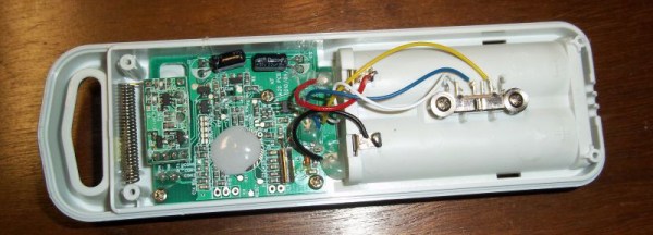
These wireless temperature sensors are exactly what you would expect for a cheap piece of Chinese electronics found in the clearance bin at Walmart. There’s a small radio operating at 433MHz, a temperature sensor, and a microcontroller under a blob of epoxy. The microcontroller and transmitter board in the temperature sensor were only attached by a ribbon cable, and each of the lines were labeled. After finding power and ground, [bhunting] took a scope to the wires that provided the data to the radio and took a look at it with a logic analyzer.

After a bit of work, [bhunting] was able to figure out how the temperature sensor sent data back to the base station, and with a bit of surgery to one of these base stations, he had a way to read the temperature data with an Arduino. From there, it’s just a data logging problem that’s easily solved with Excel, and [bhunting] has exactly what he originally wanted, thanks to a find in the Walmart clearance bin.

Custom Case Made Entirely Out Of PCBs

So you’ve finished your project. You’ve got a wonderful circuit, a beautiful PCB, and everything works perfectly. You’re done right? Well, maybe not. Sure, a bare PCB might be fine for a dev board, but what if you have a LCD to mount, a knob that needs turning, and buttons that need pressing. Yeah, that potentiometer hanging off the board by a few wires isn’t so pretty, is it? So it’s time for a case. Yuck. We all hate modifying cases.

[Electrodacus] came up with a clever solution in the form of stacking PCBs to form a case. In his project, he actually has the circuitry spread across 3 PCBs, and uses surface mount connectors to connect them in a stack. Along the edges are specifically shaped PCBs to complete the enclosure. This technique could be used with only one PCB containing all the circuitry, and the others acting as the case sides and top.

In this solar battery management project, the base layer has most of the power circuitry. This layer uses an aluminum metal core PCB for heat dissipation. The center layer is home for the micro controller and supporting components. And the top layer is the “front panel” with capacitive touch buttons and a cut out for a LCD. The top layer silk screen contains the logo, button markings, and the pin out of all the connectors.

If you hate drilling and filling cases (as much as we do), this technique might be right for your next project.

[via EEVBlog Forums]

OK Google, Open Sesame

There are a myriad of modern ways to lock and unlock doors. Keypads, Fingerprint scanners, smart card readers, to name just a few. Quite often, adding any of these methods to an old door may require replacing the existing locking mechanism. Donning his Bollé sunglasses allowed [Dheera] to come up with a slightly novel idea to unlock doors without having to change his door latch. Using simple, off the shelf hardware, a Smartwatch, some code crunching and a Google Now app, he was able to yell “OK Google, Open Sesame” at his Android Wear smartwatch to get his apartment  door to open up.

The hardware, in his own words, is trivial. An Arduino, an HC-05 bluetooth module and a servo. The servo is attached to his door latch using simple hardware that looks sourced from the closest hardware store. The code is split in to two parts. The HC-05 listens for a trigger signal, and informs the Arduino over serial. The Arduino in turn activates the servo to open the door. The other part is the Google Now app. Do note that the code, as he clearly points out, is “barebones”. If you really want to implement this technique, it would be wise to add in authentication to prevent all and sundry from opening up your apartment door and stealing your precious funky Sunglasses. Watch a video of how he put it all together after the break. And if you’re interested, here are a few other door lock hacks we’ve featured in the past.

Continue reading “OK Google, Open Sesame”

Nordic NRF24L01+ – Real Vs Fake

[zeptobars], the folks behind all the decapping hard work and amazing die shots are at it again. This time they decided to look under the hood of two identical looking Nordic nRF24L01+ chips.

The nRF24L01+ is a highly integrated, ultra low power (ULP) 2Mbps RF transceiver IC for the 2.4 GHz ISM (Industrial, Scientific and Medical) band. Popular, widely used and inexpensive – and the counterfeit foundries are drawn to it like honey bees to nectar. But to replicate and make it cheaper than the original, one needs to cut several corners. In this case, the fakes use 350 nm technology, compared to 250 nm in the original and have a larger die size too.

These differences mean the fakes likely have higher power usage and lower sensitivities, even though they are functionally identical. The foundry could have marked these devices as Si24R1, which is compatible with the nRF24L01 and no one would have been wiser. But the lure of higher profits was obviously too tempting. A look through Hackaday archives will dig up several posts about the work done by [zeptobars] in identifying fake semiconductors.

Castellated Breakout Is Pitchin’ Brilliant!

Radio, WiFi and similar modules are getting smaller by the day. Trouble is, they end up having non-DIY-friendly, odd pitch, mounting pads. Sometimes, though, simple hacks come around to help save the day.

[Hemal] over at Black Electronics came up with a hack to convert odd-pitch modules to standard 2.54mm / 0.1″. The process looks simple once you see the detailed pictures on his blog. He’s using the technique to add 2mm pitch modules like the ESP8266 and XBee by soldering them to standard perf board. Once they are hooked to the board, just add a row of male header pins, trim the perf board and you’re done. Couldn’t get simpler.

Another technique that we’ve seen is to solder straight across the legs and cut the wire afterward. That technique is also for protoyping board, but custom-sized breakout boards are one good reason to still keep those etchants hanging around. If you have other techniques or hacks for doing this, let us know in the comments.

Hack Allows ESP-01 To Go To Deep Sleep

The ESP-01 module based on the ESP8266 is all the rage with IoT folks at the moment – and why not. For about 5 bucks, it can’t be beat on price for the features it offers. The one thing that such radios do a lot is suck power. So, it’s no surprise that ways to cut down on the juice that this device consumes is top priority for many people. [Tim] figured out a simple hardware hack to get the ESP-01 to go to deep sleep, effectively reducing its current draw to 78uA – low enough to allow battery powered deployment.

While [Tim] was working on understanding the ESP8266 tool chain (NodeMCU firmware > Lua interpreter > ESPlorer IDE), he realized that some essential pins weren’t accessible on the ESP-01 module. [Tim] built a Dev board on perf board that let him access these pins and also added some frills while at it. We’re guessing he (or someone else) will come up with a proper PCB to make things easier. But the real hack is on the ESP-01 module itself. [Tim] needed to hardwire the ‘post-sleep-reset-pin’ on the MCU to the Reset terminal. That, and also pry off the indicator LED’s with a screw driver! That sounds a bit drastic, and we’d recommend pulling out your soldering iron instead. If you’re one of the unlucky one’s to receive the “magic smoke” releasing ESP8266 modules, then you don’t need the LED anyway.

Hacking The Nike+ Fuelband

[Simone] was trying to reverse-engineer the Bluetooth protocol of his Nike+ Fuelband and made some surprising discoveries. [Simone] found that the authentication system of the Fuelband can be easily bypassed and discovered that some low-level functions (such as arbitrarily reading and writing to memory) are completely exposed to the end user or anyone else who hacks past the authentication process.

[Simone] started with the official Nike app for the Fuelband. He converted the APK to a JAR and then used JD-Gui to read the Java source code of the app. After reading through the source, he discovered that the authentication method was completely ineffective. The authenticator requires the connecting device to know both a pin code and a nonce, but in reality the authentication algorithm just checks for a hard-coded token of 0xff 0xff 0xff 0xff 0xff 0xff rendering the whole authentication process ineffective.

After he authenticated with the Fuelband, [Simone] started trying various commands to see what he could control over the Bluetooth interface. He discovered that he could send the device into bootloader mode, configure the RTC, and even read/write the first 65k of memory over the Bluetooth interface–not something you typically want to expose, especially with a broken authentication mechanism. If you want to try the exploit yourself, [Simone] wrote an Android app which he posted up on GitHub.