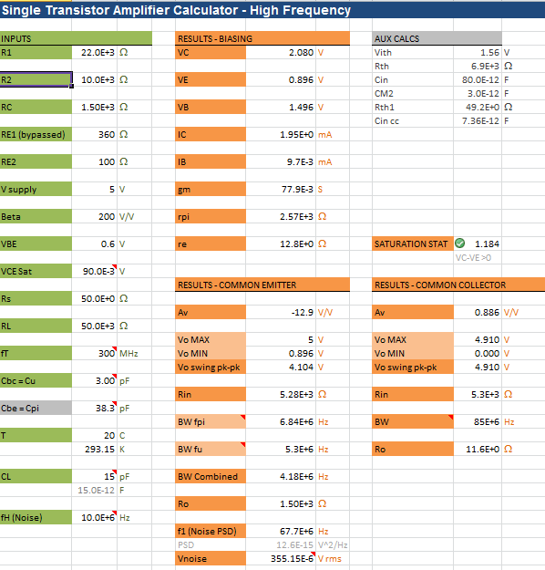
Reverse Engineering Unobtanium

font

If you listen to [Bil Herd] and the rest of the Commodore crew, you’ll quickly realize the folks behind Commodore were about 20 years ahead of their time, with their own chip foundries and vertical integration that would make the modern-day Apple jealous. One of the cool chips that came out of the MOS foundry was the 6500/1 – used in the keyboard controller of the Amiga and the 1520 printer/plotter. Basically a microcontroller with a 6502 core, the 6500/1 has seen a lot of talk when it comes to dumping the contents of the ROM, and thus all the code on the Amiga’s keyboard controller and the font for the 1520 plotter – there were ideas on how to get the contents of the ROM, but no one tried building a circuit.

[Jim Brain] looked over the discussions and recently gave it a try. He was completely successful, dumping the ROM of a 6500/1, and allowing for the preservation and analysis of the 1520 plotter, analysis of other devices controlled by a 6500/1, and the possibility of the creation of a drop-in replacement for the unobtanium 6500/1.

The datasheet for the 6500/1 has a few lines describing the test mode, where applying +10 VDC to the /RES line forces the machine to make memory fetches from the external pins. The only problem was, no body knew how to make this work. Ideas were thrown around, but it wasn’t until [Jim Brain] pulled an ATMega32 off the top of his parts bin did anyone create a working circuit.

The code for the AVR puts the 6500/1 into it’s test mode, loads a single memory location from ROM, stores the data in PORTA, where the AVR reads it and prints it out over a serial connection to a computer. Repeat for every location in the 6500/1 ROM, and you have a firmware dump. This is probably the first time this code has been seen in 20 years.

Now the race is on to create a drop-in replacement of what is basically a 6502-based microcontroller. That probably won’t be used for much outside of the classic and retro scene, but at least it would be a fun device to play around with.

Pinoccio: Mesh All The (Internet Of) Things

PinnThere’s a problem with products geared towards building the Internet of Things. Everyone building hardware needs investors, and thus some way to monetize their platform. This means all your data is pushed to ‘the cloud’, i.e. a server you don’t own. This is obviously not ideal for the Hackaday crowd. Yes, IoT can be done with a few cheap radios and a hacked router, but then you don’t get all the cool features of a real Things project – mesh networking and a well designed network. Pinoccio is the first Thing we’ve seen that puts a proper mesh network together with a server you can own. The Pinoccio team were kind enough to let us drop in while we were in Rock City last weekend, and we were able to get the scoop on these tiny boards from [Sally] and [Eric], along with a really cool demo of what they can do.

The hardware on the Pinoccio is basically an Arduino Mega with a LiPo battery and an 802.15.4 radio provided by an ATmega256RFR2. The base board – technically called a ‘field scout’ – can be equipped with a WiFi backpack that serves as a bridge for the WiFi network. It’s a pretty clever solution to putting a whole lot of Things on a network, without having all the Things directly connected to the Internet.

Programming these scouts can be done through Arduino, of course, but the folks at Pinoccio also came up with something called ScoutScript that allows you to send commands directly to any or all of the scouts on the mesh network. There’s a neat web-based GUI called HQ that allows you to command, control, and query all the little nodules remotely as well.

In the video below, [Sally] goes over the basic functions of the hardware and what it’s capable of. [Eric] was in Reno when we visited, but he was kind enough to get on a video chat and show off what a network of Pinoccios are capable of by emblazoning their web page with Hackaday logos whenever he presses a button.

Continue reading “Pinoccio: Mesh All The (Internet Of) Things”

DIY Circuit Boards Look Professional

Professional Looking DIY PCB Boards

Making PCBs at home is a great means to get your prototype up and running without having to wait weeks for a professionally made board. Regardless if these prototype boards are milled or etched, they are easily identified as ‘home brew’ due to their ‘unfinished’ appearance. [HomeDIY&Stuff] has put together a little how-to on the process for making DIY PCBs look a little closer to a professionally manufactured board.

The process starts out with designing the board in a PCB program. There are a lot of these programs available. Eagle is a popular choice and has a free version available. Once the layout it finalized, the design is printed out on a transparent sheet of plastic. A blank copper-clad PCB board that already has a UV sensitive coating applied are available for purchase and is what is used in this example. The transparency is placed over the PCB blank and then exposed to UV light. The coating on the PCB cures where ever the UV light passes through the open areas of the transparency.

Once the transparency is removed, there is a noticeable difference in coating color where it has cured. This board is now placed in a developer solution that removes the un-cured UV sensitive coating. A Ferric Chloride acid bath then etches away at the now-exposed copper. The cured coating from the previous step protects the copper at the trace locations during the etch process. The result is a board with copper where you want it and none where you don’t. If the board has any through-hole components, this would be the time to drill those holes.

Up to this point the process has been pretty standard for homemade PCBs and the next part is certainly the most interesting but, unfortunately, is also the worst documented step; the solder mask and silk screening. It appears that two silk screens are produced, one for the solder mask and one for the silk screen. The artwork for making the silk screens can be output from the PCB design software. There is no mention of the solder mask material used but oil-based silk screen ink is specified. Although the details are lacking, the photos show that it works pretty well. If you have had any experience with silk screening DIY PCBs, let us know in the comments.

Mains Power Detector For A Thing For Internet

inductor The Internet of Things is fast approaching, and although no one can tell us what that actually is, we do know it has something to do with being able to control appliances and lights or something. Being able to control something is nice, but being able to tell if a mains-connected appliance is on or not is just as valuable. [Shane] has a really simple circuit he’s been working on to do just that: tell if something connected to mains is on or not, and relay that information over a wireless link.

There are two basic parts of [Shane]’s circuit – an RLC circuit that detects current flowing through a wire, This circuit is then fed into an instrumentation amplifier constructed from three op-amps. The output of this goes through a diode and straight to the ADC of a microcontroller, ready for transmission to whatever radio setup your local thingnet will have.

It’s an extremely simple circuit and something that could probably be made with less than a dollar’s worth of parts you could find in a component drawer. [Shane] has a great demo of this circuit connected to a microcontroller, you can check that out below.

Continue reading “Mains Power Detector For A Thing For Internet”

The Disintegrated Op Amp

741By now we’ve all seen the ‘Three Fives’ kit from Evil Mad Scientist, a very large clone of the 555 timer built from individual transistors and resistors. You can do a lot more in the analog world with discrete parts, and [Shane]’s SevenFortyFun is no exception: it’s a kit with a board, transistors, and resistors making a very large clone of the classic 741 op-amp, with all the parts laid bard instead of encapsulated in a brick of plastic.

[Shane] was inspired by the analog greats – [Bob Pease], [Jim Williams], and of course [Bob Widlar], and short of mowing his lawn with goats, the easiest way to get a feel for analog design was to build some analog circuits out of individual components.

[Shane] has a few more kits in mind: a linear dropout and switching regulators are on the top of the list, as is something like the Three Fives kit, likely to be used to blink giant LEDs.

The Cheapest Crystal Oven

oven

The crystals you’ll find attached to microcontrollers or RTCs are usually accurate to 100 parts per million at most, but that still means if you’re using one of these crystals as a clock’s time base, you could lose or gain a second per day. For more accuracy without an atomic clock, a good solution is an oven controlled crystal oscillator – basically, a temperature controlled crystal. It’s not hard to build one, and as [Roman] demonstrates, can be built with a transistor and a few resistors.

The heating element for this OCXO are just a few resistors placed right on the can of a crystal. A thermistor senses the heat, and with more negative feedback than the Hackaday comments section, takes care of regulating the crystal’s temperature. A trimpot is used for calibrating the temperature, but once everything is working that can be replaced with a fixed resistor.

This deadbugged circuitry is then potted in five minute epoxy. That’s a bit unconventional as far as thermal management goes, but the results speak for themselves: [Roman] can get a clock with this circuit accurate to a few seconds per year.

TI’s New Family Of WiFi Chips

cccc Texas Instruments’ CC3000 WiFi chip is the darling of everyone producing the latest and greatest Internet of Thing, and it’s not much of a surprise: In quantity, these chips are only $10 a piece. That’s a lot less expensive than the WiFi options a year ago. Now, TI is coming out with a few new modules to their WiFi module family, including one that includes an ARM micro.

The CC3000 has found a home in booster packs, breakout boards for the Arduino, and Spark, who are actually some pretty cool dudes.Still, the CC3000 has a few shortcomings; 802.11n isn’t available, and it would be really cool if the CC3000 had a web server on it.

The newest chips add these features and a whole lot more. [Valkyrie] got his hands on a CC3100Boost board and was pleased to find all the files for the webserver can be completely replaced. Here’s your Internet of Things, people. The CC3200 is even better, with a built-in ARM Cortex M4 with ADCs, a ton of GPIOs, an SD card interface, and even a parallel port for a camera. If you’re looking to pull a hardware startup out of your hat, you might want to plan your Kickstarter around this chip.

It’s all very cool stuff, and although the bare chips aren’t available yet, you can get an eval module from TI, with an FCC certified module with the crystals and antenna coming later this year.