Like a million or so other people, [Brian Dorey] picked up a third generation Echo Dot during Amazon’s big sale a couple weeks ago. Going for less than half its normal retail price, he figured it was the perfect time to explore Amazon’s voice assistant offerings. But the low price also meant that he didn’t feel so bad tearing into the thing for our viewing pleasure.
 By pretty much all accounts, the Echo Dot line has been a pretty solid performer as far as corporate subsidized home espionage devices go. They’re small, fairly cheap, and offer the baseline functionality that most people expect. While there was nothing precisely wrong with the earlier versions of the Dot, Amazon has used this latest revision of the device to give the gadget a more “premium” look and feel. They’ve also tried to squeeze a bit better audio out of the roughly hockey puck sized device. But of course, some undocumented changes managed to sneak in there as well.
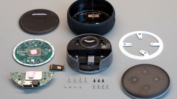
For one thing, the latest version of the Dot deletes the USB port. Hackers had used the USB port on earlier versions of the hardware to try and gain access to the Android (or at least, Amazon’s flavor of Android) operating system hiding inside, so that’s an unfortunate development. On the flip side, [Brian] reports there’s some type of debug header on the bottom of the device. A similar feature allowed hackers to gain access to some of Amazon’s other voice assistants, so we’d recommend hopeful optimism until told otherwise.
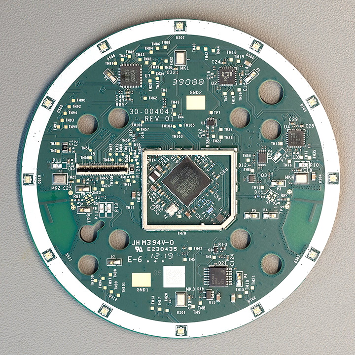
The Echo Dot is powered by a quad-core Mediatek MT8516BAAA 64-bit ARM Cortex-A35 processor and the OS lives on an 8GB Samsung KMFN60012M-B214 eMMC. A pair of Texas Instruments LV320ADC3101 ADCs are used to process the incoming audio from the four microphones arranged around the edge of the PCB, and [Brian] says there appears to be a Fairchild 74LCX74 flip-flop in place to cut the audio feed when the user wants a bit of privacy.
Of course, the biggest change is on the outside. The new Dot is much larger than the previous versions, which means all the awesome enclosures we’ve seen for its predecessor will need to be reworked if they want to be compatible with Amazon’s latest and greatest.