To give people the most intimate RBMK experience, the [Chornobyl Family] has been working tirelessly at not only replicating the original RBMK reactor control room and its SKALA industrial control system’s controls, but also to create a version that you could tinker with at home if you ever fancied getting your own RBMK operator license. This starts with the operator console, with its use demonstrated in a recent video including a range of common commands.
In this video the entering of codes on the console to interact with the system is detailed, including the logic behind it. In the absence of large displays to display many parameters and such, this way the operator could ‘talk’ with the control system, including obtaining current sensors readings and the setting and changing of setpoints. From the same console you can also select and run programs, which is useful for automating tasks, like monitoring coolant flows.
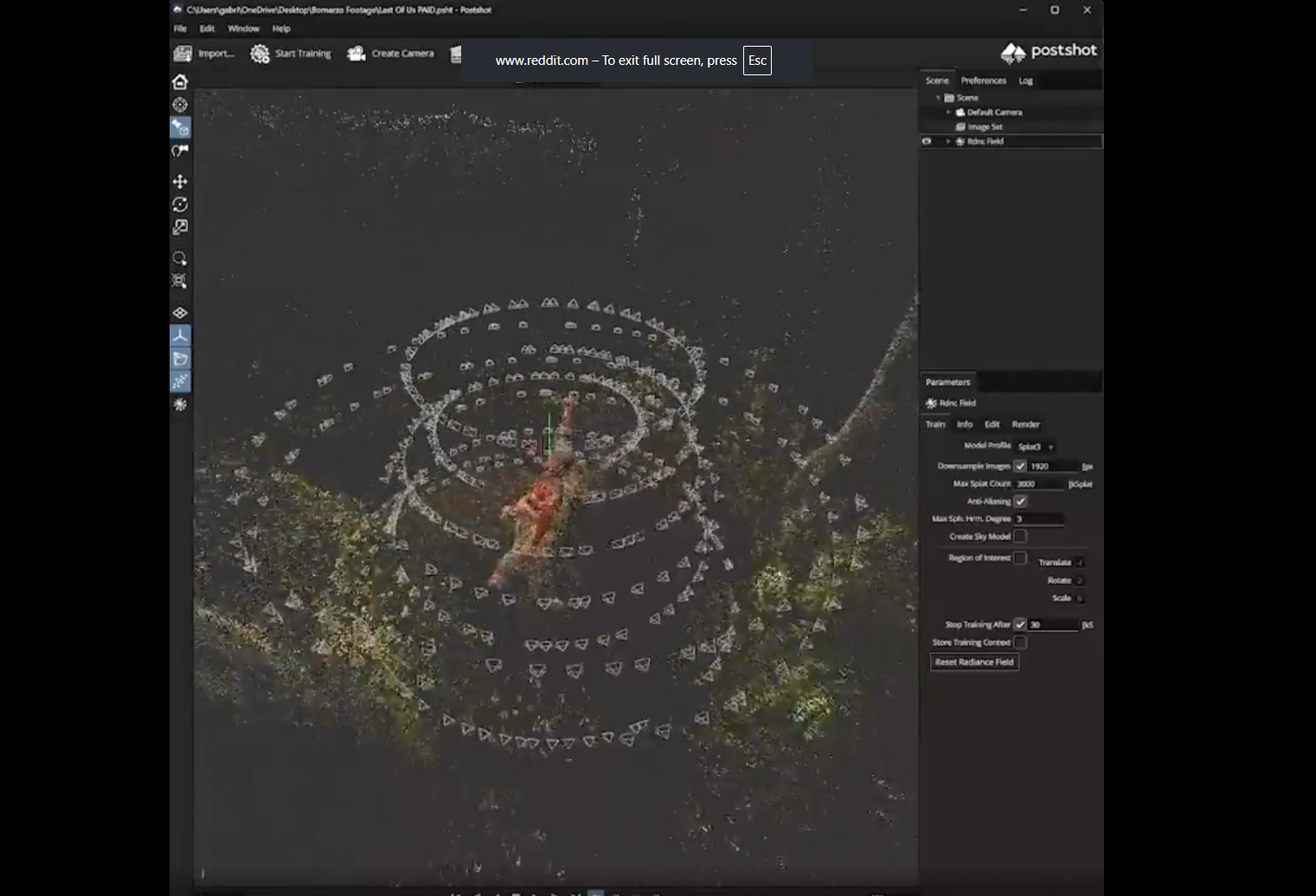
In the second video not only the construction of the control panel is covered, but also a visual representation of the simulated reactor core which is displayed on a connected monitor. Although not a part of the original SKALA system as such, a much larger version existed as a wall-sized physical version inside the control room, so it’s definitely more home-simulator friendly.
We previously covered this SKALA system that controls RBMK reactors, as well as the 1990s modernization of the Chornobyl Nuclear Power Plant.
Continue reading “Using Your Own RBMK Reactor Control Center At Home”

 Although paperbacks are a much-loved aspect of the literary world, they are not really intended to last the decades the way that hardcover books are. Beyond the typical ravaged covers, paperbacks also tend to suffer from a warped spine, where the formally flat spine gets a definite inwards curve due to the ravages of moisture, temperature, failing glue and the passing of time in general. If this bothers you, then [Book Care Studio]


 A healthy aquarium ecosystem requires very specific conditions, with factors like the salinity and temperature having to be just right to keep said ecosystem happy. As some species are adapted to fairly cold water, this requires the use a water chiller. Recently [The Blunt Oracle] modified one of these aquarium-focused chillers with