All About USB-C: Example Circuits

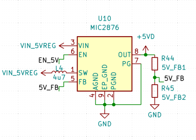
In the six months that have passed after the last USB-C article has been released, I have thought up a bunch of ways that these articles could have been improved. It’s, of course, normal to have such a feeling — expected, even. I now believe that there’s a few gaps that I could bridge. For instance, I have not provided enough example circuits, and sometimes one schematic can convey things better than a thousand words.

Let’s fix that! I’ll give you schematics for the kinds of USB-C devices you’re actually likely to want to build. I’ll also share a bunch of IC part numbers in this article, but I don’t have an exhaustive collection, of course – if you find more cool ICs that work for USB-C purposes and aren’t mentioned here, please do let us all know in the comments!

Continue reading “All About USB-C: Example Circuits”

Importing EAGLE Projects Into KiCad 7, And How To Fix Them

Migrating a PCB design from one CAD software package to another is no one’s favorite task. It almost never works cleanly. Often there are missing schematic symbols, scrambled PCB footprints, and plenty of other problems. Thankfully [shabaz] shows how to import EAGLE projects into KiCad 7 and fix the most common problems one is likely to encounter in the process. Frankly, the information couldn’t come at a better time.

This is very timely now that EAGLE has gone the way of the dodo. CadSoft EAGLE used to be a big shot when it came to PCB design for small organizations or individual designers, but six years after being purchased by Autodesk they are no more. KiCad 7 is a staggeringly capable open-source software package containing some fantastic features for beginner and advanced designers alike.

Of course, these kinds of tutorials tend to be perishable because software changes over time. So if you’re staring down a migration from EAGLE to KiCad and could use some guidance, there’s no better time than the present. [shabaz]’s video showing the process is embedded below.

Thanks to [problemchild68] for the tip!

Continue reading “Importing EAGLE Projects Into KiCad 7, And How To Fix Them”

Smart Sphere Or Magnetic Magic

Sometimes a coworker sees something on your desk, and they have to ask, “Where can I get one of those?” and that has to be one of the greatest compliments to a maker. [Greg Zumwalt] nailed it with his “Marblevator Line Follower.” Roboticists will immediately recognize a black line on a white surface, but this uses hidden mechanics instead of light/dark sensors. Check out the video after the break to see the secrets, or keep bearing with us.

Inside the cylinder is a battery, charging circuit, inductive receiving coil, and a motor turning a magnet-laden arm beneath the cap. The overall effect is an illusion to convince people that the marble has a mind of its own. You can pick up the cylinder, and it keeps moving as expected from an autonomous bot. The black line is actually a groove, so the bearing follows a curvy course without any extra movements from the magnets within. The two-tone look is super-clean, but the whimsy of a “smart bearing” makes this an all-around winner.

“Marblevator Line Follower” is not the first Marblevator we featured, and we love our bouncing-bearing baubles and music-making machines.

Continue reading “Smart Sphere Or Magnetic Magic”

Share Your Projects: Making Helpful PCBs

When it comes to things that hackers build, PCBs are a sizeable portion of our creative output. It’s no wonder – PCB design is a powerful way to participate in the hardware world, making your ideas all that more tangible with help of a friendly PCB fab. It’s often even more lovely when the PCB has been designed for you, and all you have to do is press “send” – bonus points if you can make a few changes for your own liking!

A lot of the time, our projects are untrodden ground, however, and a new design needs to be born. We pick out connectors, work through mechanical dimensions, figure out a schematic and check it with others, get the layout done, and look at it a few more times before sending it out for production. For a basic PCB, that is enough – but of course, it’s no fun to stop at ‘basic’, when there’s so many things you can do at hardly any cost.

Let’s step back a bit – you’ve just designed a board, and it’s great! It has all the chips and the connectors you could need, and theoretically, it’s even supposed to work first try. Now, let’s be fair, there’s an undeniable tendency – the more PCBs you design, the better each next one turns out, and you learn to spend less time on each board too. As someone with over two hundred PCBs under her belt, I’d like to show you a bunch of shortcuts that make your PCB more helpful, to yourself and others.

There’s a few ways that you can share your PCB projects in a more powerful way – I’d like to point out a few low-hanging fruits, whether README.md files or markings on the PCB itself. I’ve been experimenting quite a bit with external and embedded documentation of PCBs, as well as PCB sharing methods, got some fun results, and I’d like to share my toolkit through a few punchy examples and simple tricks. I’d also like to hear about yours – let’s chat! Continue reading “Share Your Projects: Making Helpful PCBs”

How To Model A Twisted Part In FreeCAD

Quick references are handy, but sometimes it’s nice to have a process demonstrated from beginning to end. In that spirit, [Darren Stone] created a video demonstrating how to model a twisted part in FreeCAD, showing the entire workflow of creating the part as a blend of surfaces and curves that get turned into a solid.

FreeCAD is organized using the concept of multiple “workbenches” which are each optimized for different tools and operations, and [Darren] walks through doing the same jobs in a few different ways.

This twisted bracket is a simple part that is nevertheless nontrivial from a CAD perspective, and that makes it a good candidate for showing off the different workbenches and tools.

The video below is also pretty good overall demonstration of what designing a part from a mechanical drawing looks like when done in FreeCAD. As for mechanical drawings themselves, we’ve seen FreeCAD can be used to make those, too.

Continue reading “How To Model A Twisted Part In FreeCAD”

FET: The Friendly Efficient Transistor

If you ever work with a circuit that controls a decent amount of current, you will often encounter a FET – a Field-Effect Transistor. Whether you want to control a couple of powerful LEDs, switch a USB device on and off, or drive a motor, somewhere in the picture, there’s usually a FET doing the heavy lifting. You might not be familiar with how a FET works, how to use one and what are the caveats – let’s go through the basics.

Here’s a simple FET circuit that lets you switch power to, say, a USB port, kind of like a valve that interrupts the current flow. This circuit uses a P-FET – to turn the power on, open the FET by bringing the GATE signal down to ground level, and to switch it off, close the FET by bringing the GATE back up, where the resistor holds it by default. If you want to control it from a 3.3 V MCU that can’t handle the high-side voltage on its pins, you can add a NPN transistor section as shown – this inverts the logic, making it into a more intuitive “high=on, low=off”, and, you no longer risk a GPIO!

This circuit is called a high-side switch – it enables you to toggle power to a device at will through a FET. It’s the most popular usecase for a FET, and if you’re wondering more about high-side switches, I highly recommend this brilliant article by our own [Bil Herd], where he shows you high-side switch basics in a simple and clear way. For this article, you can use this schematic as a reference of how FETs are typically used in a circuit.

Continue reading “FET: The Friendly Efficient Transistor”

Make Your ESP32 Talk Like It’s The 80s Again

80s-era electronic speech certainly has a certain retro appeal to it, but it can sometimes be a useful data output method since it can be implemented on very little hardware. [luc] demonstrates this with a talking thermometer project that requires no display and no special hardware to communicate temperatures to a user.

Back in the day, there were chips like the Votrax SC-01A that could play phonemes (distinct sounds that make up a language) on demand. These would be mixed and matched to create identifiable words, in that distinctly synthesized Speak & Spell manner that is so charming-slash-uncanny.

Software-only speech synthesis isn’t new, but it’s better now than it was in Atari’s day.

Nowadays, even hobbyist microcontrollers have more than enough processing power and memory to do a similar job entirely in software, which is exactly what [luc]’s talking thermometer project does. All this is done with the Talkie library, originally written for the Arduino and updated for the ESP32 and other microcontrollers. With it, one only needs headphones or a simple audio amplifier and speaker to output canned voice data from a project.

[luc] uses it to demonstrate how to communicate to a user in a hands-free manner without needing a display, and we also saw this output method in an electric unicycle which had a talking speedometer (judged to better allow the user to keep their eyes on the road, as well as minimizing the parts count.)

Would you like to listen to an authentic, somewhat-understandable 80s-era text-to-speech synthesizer? You’re in luck, because we can show you an authentic vintage MicroVox unit in action. Give it a listen, and compare it to a demo of the Talkie library in the video below.

Continue reading “Make Your ESP32 Talk Like It’s The 80s Again”