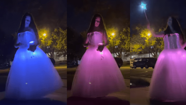
[Kellechu] went full parent beast mode by creating a prom dress for her daughter. This incredible build is a tour-de-force of DIY crafting, combining sewing, electronics, 3D printing and programming.
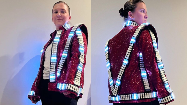
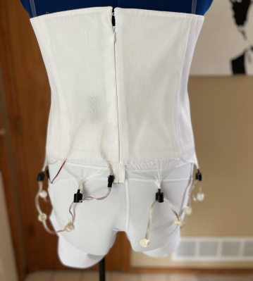
The dress skirt is made of tulle that allows for the LED strip underneath to diffuse through. The top bodice is made of fiber optic fabric sewn between the fabric form with the dangling fiber optic threads grouped into bundles. The dangling fiber optic bundles were then inserted and glued into “out caps” that forced the strands to sit next to a NeoPixel LED. A 20 NeoPixel “Dots Strand” strip was strung around the waist line, affixing 12 of the NeoPixels with an “out cap” to light up the fiber optic bodice. The remaining NeoPixels were outfitted with a diffuser cap and hung lower to light up the tulle skirt portion of the dress.
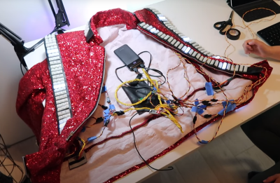
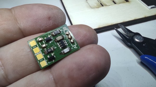
A wand was 3D printed and housed with an RFM69HCW Packet Radio M0 Feather, a NeoPixel LED color ring and a TCS34725 Flora color sensor powered by a 2.2 Ah 3.7 V LiPo battery. Another RFM69HCW Packet Radio M0 Feather was placed in the dress to be able to receive messages from the wand so that the sensed color could be transmitted and the LED strip could be updated with the sensed color. The dress portion was powered by a 10 Ah 3.7 V LiPo, with the battery and electronics fitting snugly into yoga bike shorts with side pockets.
[Kellechu]’s Instructable is full of details about the process and is worth checking out. For example, [Kellechu] goes into detail about the troubles and care taken when dealing with the different media, making sure to avoid ironing the fiber optics so as not to melt the lines and experimenting with different sewing needles to limit the amount of dead fibers as collateral damage from the sewing process.
Dresses with LEDs and other lights are a big hit, as can be seen from our feature on an LED wedding dress.
Continue reading “Be The Star Of The Evening With This Light Up Prom Dress”