The smartphone is perhaps the signature device of our modern lives. For most of the population it is never more than an arm’s length away, it’s on your person more than any other device in your life. Smartphones are packed with all sorts of radios and ways to communicate wireless. [Amine Mansouri] built an ESP8266 based tracking device that takes advantage of this.
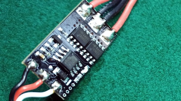
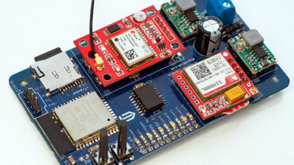
Most WiFi-enabled devices will send out “probe requests” frames trying to search for the SSIDs they were connected to. These packets contain the device MAC address as well as the SSIDs you’ve connected to. Using about 12 components, [Amine] laid out a small board in Eagle. By putting the ESP8266 in monitor mode, the probe frames can be logged and uploaded. The code can be updated OTA making it easy to service while in the field.
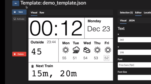
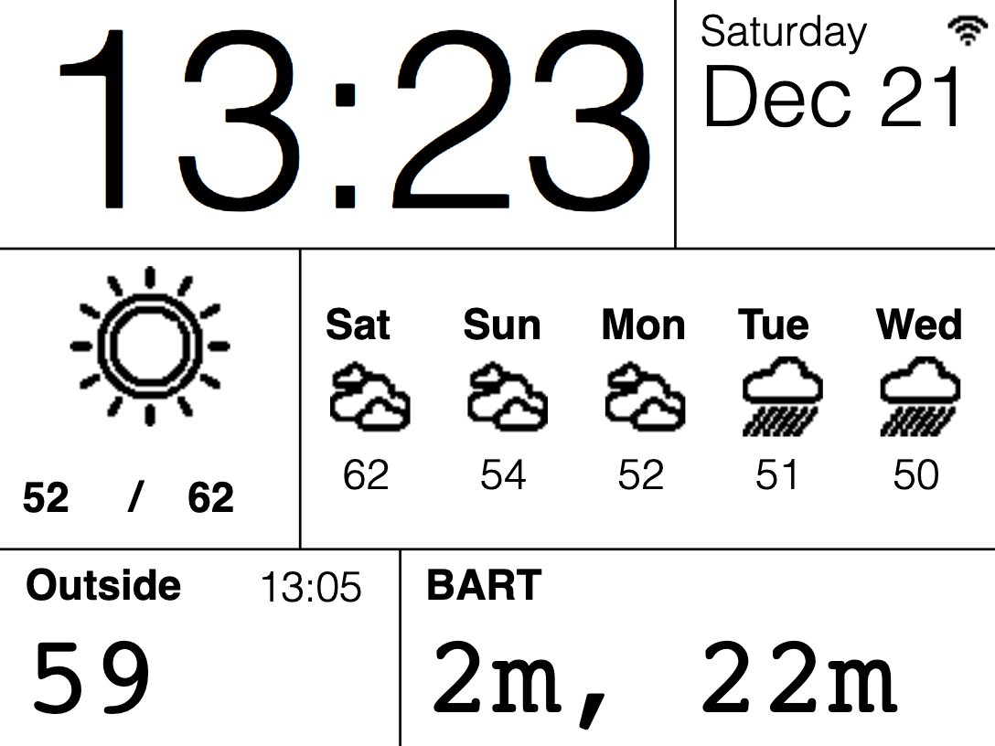
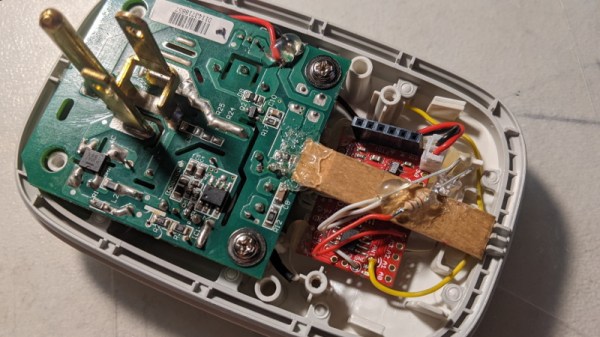
With permission from his local library, eight repeater boards were scattered throughout the building to forward the probe packets to where the tracker could pick them up. A simple web interface was built that allows the library to figure out how many people are in the library and how often they frequent the premises.
While an awesome project with open-source code on Github, it is important to stress how important is it to get permission to do this kind of tracking. While some phones implement MAC randomization, there are still many out in the wild that don’t. While this is similar to another project that listens to radio signals to determine the coming and going of ships and planes, tracking people with this sort of granularity is in a different category altogether.
Thanks [Amine] for sending this one in!

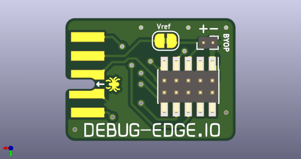
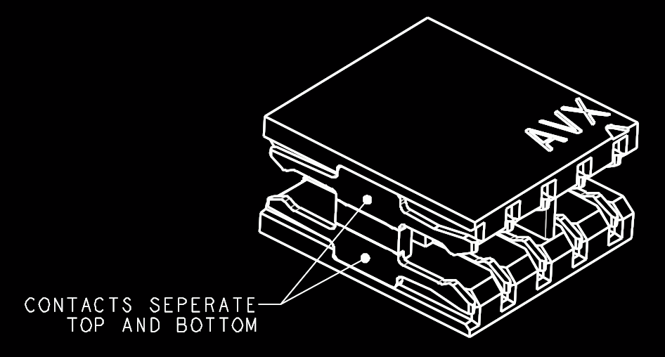 The name “Debug Edge” says it all. It’s a debug, edge connector. A connector for the edge of a PCBA to break out debug signals. Card edge connectors are nothing new but they typically either slot one PCBA perpendicularly into another (as in a PCI card) or hold them in parallel (as in a mini PCIe card or an m.2 SSD). The DebugEdge connector is more like a PCBA butt splice.