Sort The Rainbow With An Algorithm Machine

When you’re trying to learn how an algorithm works, it’s not always easy to visualize what’s going on. Well, except for maybe binary sort, thanks to the phone book. Professor [thatguyer] is a computer science teacher who wanted a way to help his students visualize the process of algorithms and at the same time, get a grasp on their resource cost.

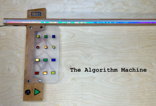
The Algorithm Machine can demonstrate 8 different search and sort algorithms using two 100-count strips of RGB LEDs — one to represent an array of integers, and one to create indicators pointing to the integers under scrutiny.

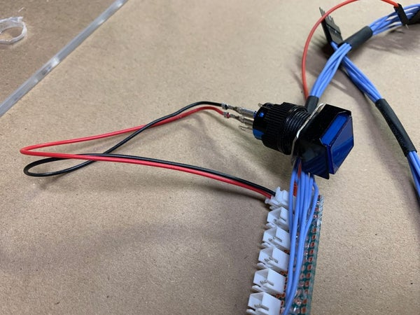
This functional beauty is totally interactive, too. Once the user chooses the values and the algorithm and starts the process, they can speed it up or slow it down with the rotary encoder, or pause to discuss and start again with that slick triangular play button. We particularly like the control button wiring harness [thatguyer] created to keep everything neat and hot-swappable.

This iteration uses 3D printed face plates to give the LEDs shape, but in an early version, [thatguyer] cut and sanded a ton of circles out of brass tubing, and folded as many triangles cut from disposable baking pans. The world could use more teachers as committed as [thatguyer]. This really seems like a handy teaching aid for these concepts, and we wish we’d had one in class to play around with. Here’s your algorithm for watching the demo: click break, press play, enjoy.

If you’re still confused, there are other ways to understand algorithms through visualization. Failing all that, just watch these Hungarian folk dancers work out various algo-rhythms.

Continue reading “Sort The Rainbow With An Algorithm Machine”

This PIC Is A Squarewave Generator

When we use a microcontroller to flip a few GPIOs or talk SPI to a peripheral chip, we are often overlooking that it will usually contain an array of built-in peripherals that were once the preserve of extra hardware. Analogue ports, timers, UARTs, and clock generators, to name just a few. [Giovanni Bernardo] has been experimenting with one of these, the internal frequency synthesiser on many PIC microcontrollers, and he’s  produced a handy square wave generator for which he’s placed code on GitHub and produced a write-up (Italian language, Google translate link).

The board used is a PIC16F375 Curiosity Nano, and code takes input from a rotary encoder to set the frequency, with a button to select different step sizes and an alphanumeric LCD display to show the current settings. Frequencies from 1 Hz to 15 MHz are possible, with a clever switch between two of the PICs internal clocks to be used as the reference frequency. Stability depends upon whatever source the PIC uses for its own clock, and while we suspect that will be enough for most users it’s not inconceivable that the PIC could be clocked from a GPS-disciplined source or similar were there a requirement for it.

There are plenty of ways to generate square waves from a microcontroller. Most projects use waveform generator ICs.

Old Rotary Phone Gets Called Into Action

The more glass we punch with our fingertips, the more we miss fun physical interfaces like the rotary phone. Sure, they took forever to dial, and you did not want to be one of those kids stuck with one during the transition to DTMF, especially if you were trying to be the 9th caller to a radio station, but the solidly electromechanical experience of it all was just cool, okay? The sound and the heft made them seem so adult.

[Tal O] gets it. He’s all but finished bringing this old girl into the 21st century without giving anything away on her surface. Inside are some things you’d expect, like a SIM800 GSM module for the telephony part, and an ESP32 to count the pulses from the dialer and communicate between it and the GSM module. But it also has a few things we haven’t seen before. The entire journey is outlined in a five-part video series, and we’ve got part one dialed in for you after the break.

Although [Tal] got the ringer working to prove it could be done, he didn’t want to have a separate 12V circuit just to run the bells. Also, the bells and their electromagnets take up a lot of space, so he compromised with an mp3 of a rotary ringer. [Tal] also wanted a way to have dialed-number feedback without cutting up the phone to add a screen, so he found a text-to-speech library and made the phone speak each number aloud as soon as it’s dialed. It uses the same internal speaker as the ringer, but we think it would be neat if the feedback came through the handset speaker.

If [Tal] is looking for another modern convenience to add to this phone, how about speed dial?

Continue reading “Old Rotary Phone Gets Called Into Action”

Microcontroller Studies The Blade

Kendo, a Japanese martial art, is practiced with a special sword. It’s not a particularly sharp sword, though, since the “blade” is essentially a length of bamboo. For this reason, Kendo practitioners must rely on correct form and technique in order to make sure their practice is as effective as possible, and Cornell students [Iman] and [Weichen] have made a Kendo trainer that helps the swordsmen in their art.

The core of the project is a PIC32 microcontroller hooked up to a set of three piezoelectric sensors and a LSM9DS1 inertial module. The three piezoelectric sensors are attached to a helmet and the inertial module to the sword, and the sensors work together to determine both the location of the strike and whether or not it had enough strength to be considered a “good” strike (the rules of Kendo are beyond the scope of this article). The trainer can then calculate all of the information and provide feedback to the user on a small screen.

While martial-arts related builds seem to be relatively rare, we did find a similar project from back in 2011 called the Virtual Sensei which used a then-popular Kinect in order to track movements. This PIC32-based project, though, seems to be a little more thorough by including the strength of the strike in the information the computer uses, and is probably less expensive to boot!

Continue reading “Microcontroller Studies The Blade”

A Nano With An Otter’s Bite

The would-be microcontroller experimenter is now faced with a bewildering array of choices when it comes to a tiny development board for their projects. Everything from descendants and clones of the original Arduino through to full-fat Linux powerhouses such as the Raspberry Pi Zero and similar boards can be had, and often for a reasonable price.

A new entrant has now joined the fray, the OtterPill is an STM32F072-based board with an Arduino-Nano-like pinout, and it comes from the bench of [Jana Marie]. With so many competitors you might ask yourself what it can offer, and it would be a valid point given that a Nano clone can be had for relative pennies. Aside from the Nano shield compatibility and extra power of the ARM Cortex M0 then, it’s an open source development board with USB-PD included from its USB-C socket, and with some elite BoM wizardry she’s managed to get the cost of its components to below three dollars. A USB-PD example firmware is available and a blank firmware is on its way. For now the board exists only in prototype form, but she’s putting together a production run if you would like one too. We saw an early development of it at eth0 back in the autumn, and given the progress since then we’re sure that we won’t have to wait for long.

Regular readers will recognise [Jana Marie]’s work, because otter-themed boards have made their way to these pages before. Our most recent ones were the USB-C replacement board bringing USB-PD to the TS-100 soldering iron, and  a nifty little USB board for addressable LEDs.

Poking Around The Wide World Of Bluetooth

Bluetooth is a technology with a very interesting history. When it first came around in the late 1990s, it promised to replace the mess of wires that was tucked behind every desk of the day. Unfortunately, the capabilities of early Bluetooth didn’t live up to the hype, and it never quite took off. It wasn’t until the rise of the smartphone more than a decade later that Bluetooth, now several versions more advanced, really started to make sense.

As [Larry Bank] explains in a recent blog post, that means there’s a whole lot to learn if you want to really understand Bluetooth hacking. For example, the Bluetooth versions that were used in the 1990s and 2000s are actually a completely different protocol from that which most modern devices are using. But the original protocol, now referred to as “Classic”, is still supported and in use.

That means to really get your head wrapped around working with Bluetooth, you need to learn about the different versions and all the tools and tricks associated with them. To that end, [Larry] does a great job of breaking down the primary versions of Bluetooth and the sort of tools you might find yourself using. That includes microcontrollers such as the ESP32 or Arduino Nano 33 BLE.

But the post isn’t just theory. [Larry] also goes over a few real-world projects of his that utilize Bluetooth, such as getting a portable printer working with his Arduino, or figuring out how to use those tiny mobile phone game controllers for his own purposes. Even if you don’t have these same devices, there’s a good chance that the methods used and lessons learned will apply to whatever Bluetooth gadgets you’ve got your eye on.

Readers may recall [Larry] from our previous coverage of his exploits, such as his efforts to increase the frame rate of the SSD1306 OLED display or his wireless bootloader for the SMART Response XE. Whenever we see his name pop up in the Tip Line, we know a fascinating hardware deep dive isn’t far behind.

Stylish Thermometer Is DIY Hardware Perfection

Over the last few years, we’ve seen a steady improvement in the sort of custom hardware a dedicated individual can produce. With affordable desktop 3D printers and PCB fabrication services, the line between store bought and home built can get very blurry. This slick MQTT-connected thermometer created by [Martin Cerny] is a perfect example.

The case for the device, which [Martin] calls Temper, is printed in a stone-look PLA filament and has been carefully designed so that LEDs shining behind it illuminate perfect square “pixels” on the front. There’s a living hinge button on the left side, and on the right, an opening for the SHT30 temperature and humidity sensor. Some may say that the look of the sensor aperture could be improved with a printed grille, but there was likely a concern about reduced airflow.

Inside the case is a 13×7 array of SMD LEDs, a few 74HC595 shift registers, a TP4054 charging chip to keep the internal 250 mAh battery topped off via USB, and some passives to round out the party. The ESP-12E module that brings it all together and the battery are on the flip side of the PCB. At a press of the button, the display fires up for 5 seconds and Temper publishes temperature, humidity and battery percentage through MQTT. If you’re looking for more granular data, it can also be configured to publish regular updates at the cost of increased energy consumption.

The physical product is gorgeous on its own, but we’re happy to report that the firmware and documentation have been handled with a similar attention to detail. The project’s GitHub repo has a Wiki to help others build and configure their very own Temper, and the device’s web configuration portal is easily just as nice as anything you’d find in a piece of modern consumer electronics (if not moreso).

We’ve seen plenty of ESP8266-based environmental monitoring devices here at Hackaday, but we think this one really pushes the state-of-the-art forward. This is a device that wouldn’t be out of place on the shelf at a Big Box electronics retailer, and while [Martin] says he has no interest in building and selling them himself, we don’t doubt that folks out there will be spinning up their own Temper clones before too long.