DIY Thermal Imager Uses DIY Gaussian Blur

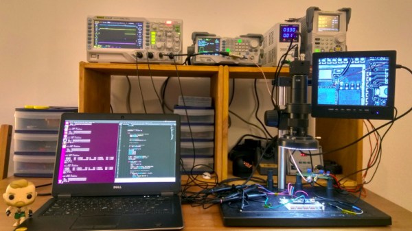
Under the right circumstances, Gaussian blurring can make an image seem more clearly defined. [DZL] demonstrates exactly this with a lightweight and compact Gaussian interpolation routine to make the low-resolution thermal sensor data display much better on a small OLED.

[DZL] used an MLX90640 sensor to create a DIY thermal imager with a small OLED display, but since the sensor is relatively low-resolution at 32×24, displaying the data directly looks awfully blocky. Gaussian interpolation to improve the display looks really good, but it turns out that the full Gaussian interpolation isn’t a trivial calculation write on your own. Since [DZL] wanted to implement it on a microcontroller, the lightweight implementation was born. The project page walks through the details of Gaussian interpolation and how some effective shortcuts were made, so be sure to give it a look.

The MLX90640 sensor also makes an appearance in the Open Thermal Camera, one of the entries for the 2019 Hackaday Prize. If you’re interested in thermal imaging, don’t miss this teardown of a thermal imaging camera.

Tiny ESP32 Fits Inside USB-A Connector

The ESP32 was introduced a few years ago as an inexpensive way to outfit various microcontrollers with WiFi or Bluetooth. Since then it has been experimented with and developed on, thanks to its similarities to the ESP8266 and the ability to easily program it. Watching the development of this small chip has truly been fascinating as it continues to grow. Or, in this case, shrink.

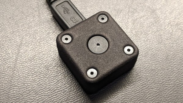
The latest development in the ESP32 world comes from [femtoduino] who, as the name suggests, makes very small things. This one is a complete ESP32 which fits inside a USB-A connector. The brains of the projects is the ESP32-D2WD which is a dual core chip with 2 Mb of memory, making it more than capable. In fact, a big part of this project was [femtoduino]’s modifications to MicroPython in order to allow it to run on this chipset. For that alone, it’s cool.

This project is impressive for both reasons, both the size and the addition to the MicroPython libraries. If you need something really really tiny, for whatever reason, you might want to look into picking up one of these. Be careful though, and be sure to get the latest version of the SDK.

Review: OSEPP STEM Kit 1, A Beginner’s All-in-One Board Found In The Discount Aisle

As the name implies, the OSEP STEM board is an embedded project board primarily aimed at education. You use jumper wires to connect components and a visual block coding language to make it go.

I have fond memories of kits from companies like Radio Shack that had dozens of parts on a board, with spring terminals to connect them with jumper wires. Advertised with clickbait titles like “200 in 1”, you’d get a book showing how to wire the parts to make a radio, or an alarm, or a light blinker, or whatever.

The STEM Kit 1 is sort of a modern arduino-powered version of these kits. The board hosts a stand-alone Arduino UNO clone (included with the kit) and also has a host of things you might want to hook to it. Things like the speakers and stepper motors have drivers on board so you can easily drive them from the arduino. You get a bunch of jumper wires to make the connections, too. Most things that need to be connected to something permanently (like ground) are prewired on the PCB. The other connections use a single pin. You can see this arrangement with the three rotary pots which have a single pin next to the label (“POT1”, etc.).

I’m a sucker for a sale, so when I saw a local store had OSEPP’s STEM board for about $30, I had to pick one up. The suggested price for these boards is $150, but most of the time I see them listed for about $100. At the deeply discounted price I couldn’t resist checking it out.

So does an embedded many-in-one project kit like this one live up to that legacy? I spent some time with the board. Bottom line, if you can find a deal on the price I think it’s worth it. At full price, perhaps not. Join me after the break as I walk through what the OSEPP has to offer.

Continue reading “Review: OSEPP STEM Kit 1, A Beginner’s All-in-One Board Found In The Discount Aisle”

LoRa-Based Plant Monitoring

Croatian engineers [Slaven Damjanovic] and [Marko Čalić] have developed a wireless system for farmers to monitor plant conditions and weather along their agricultural fields. The system uses an RFM95W module for LoRa communication, and devices are designed to be plug-and-play, battery-powered, and have long-range communication (up to 10km from the gateway).

It uses an ATMega328 microprocessor, and includes sensors for measuring soil moisture (FC28 sensor), leaf moisture (FC37 sensor), pressure (BME280 sensor), and air temperature and humidity (DHT22 or SHT71 sensor). The data is sent to a multichannel The Things Network  gateway that forwards the information to an external database, which then displays the data through a series of graphs and tables.

The software for sending messages to the gateway is based on the LoRa MAC in C (LMIC) and LowPower libraries and was developed by [ph2lb].

Continue reading “LoRa-Based Plant Monitoring”

What’s Your Fidget Spinner Say?

The persistence of vision (POV) optical illusion is pretty common in cheap toys nowadays, but how cool would it be to have your own programmable POV message board? German electronics grad student [Matej] has luckily created an open source fidget spinner with a fully customizable POV display that lets you share whatever thoughts you’d like fellow fidget spinning friends to know.

The displayed graphics don’t rely on rotation velocity, thanks to a solution that tracks the rotation angle. Unlike over POV devices, the POV fidget spinner displays the same graphics at higher and lower rotational speeds, which is useful considering the fidget spinner doesn’t automatically spin at the same rotational speed for every user. It also doesn’t require a constant speed for the image to be displayed correctly, unlike POV fans or clocks.

Continue reading “What’s Your Fidget Spinner Say?”

Punch Through Switches Gears, Shucks Beans

Do you own a LightBlue Bean or Bean+ from Punch Through? If you don’t have one now, you probably never will, as the company has recently announced they’re no longer selling or supporting the Bluetooth Low Energy microcontrollers. The company says that after selling more than 100,000 Bean devices, the challenge of keeping up with a constantly evolving software ecosystem became too difficult, and they are instead going to focus their efforts on advising other companies on how to best develop Bluetooth products.

Frankly, that sounds a bit like getting advice on how to build a fully armed and operational battle station from the Empire, but who are we to judge. While the Bean family of devices clearly wasn’t able to go the distance, Punch Through at least got them out the door and supported them for longer than many might have expected given the increased competition in the BLE market. It’s not hard to do the math: the LightBlue Bean retailed for around $35 USD, and today you can get a BLE-capable ESP32 for five bucks.

So what happens to all those Beans out in the wild? Normally, the parent company dropping support for a microcontroller wouldn’t be that big of a deal, but this time around we have the “Bean Loader” to contend with. This piece of software is used to push code to the device over Bluetooth, and it’s possible that the constant march of operating system upgrades (especially on mobile devices) will eventually break it. Long story short, there’s nothing to worry about in the short term. But down the road, these Beans might be baked.

Luckily, Punch Through did provide some pretty extensive documentation for the Beans. If there’s significant demand, we imagine the community will do their best to take over development of whatever ancillary software is required to keep the hardware usable for the foreseeable future. Speaking of which, the schematics and PCB layouts for both the Bean and Bean+ have been released under the Creative Commons Attribution 4.0 International license, so it’s not outside the realm of possibility that somebody else might put them back into production.

[Thanks to Chris for the tip.]

Speeding Up Drawing To MCU-Connected Serial Displays

Writing image data to serially connected (SPI/I2C) displays from a microcontroller is easy enough these days, courtesy of standards defined by the MIPI Alliance, yet there are some gotchas in it which may catch someone using it unaware. [Larry Bank] wrote up a good summary of how one can get maximum performance out of such a display link.

At the core is the distinction between pixel data and command transmissions. The change from command to pixel data mode requires signaling, which takes precious clock cycles away from transferring pixel data between the MCU and display. The common MIPI DCS instruction set allows for a big reduction in needed data transfers by allowing parts of the display to be addressed instead of requiring a full refresh. Yet by not properly segmenting command and data transfers, one ends up unnecessarily slowing down the process.

The result is that one can run something like a Pac-Man emulator on an AVR MCU with a sluggish 320×480 SPI LCD at 60 FPS, as one can see in the video that is embedded after the break. Check the article for another demo video as well.

Continue reading “Speeding Up Drawing To MCU-Connected Serial Displays”