Simple ESP8266 Weather Station Using Blynk

Today’s hacker finds themself in a very interesting moment in time. The availability of powerful microcontrollers and standardized sensor modules is such that assembling the hardware for something like an Internet-connected environmental monitor is about as complex as building with LEGO. Hardware has become elementary in many cases, leaving software as the weak link. It’s easy to build the sensor node to collect the data, but how do you display it in a useful and appealing way?

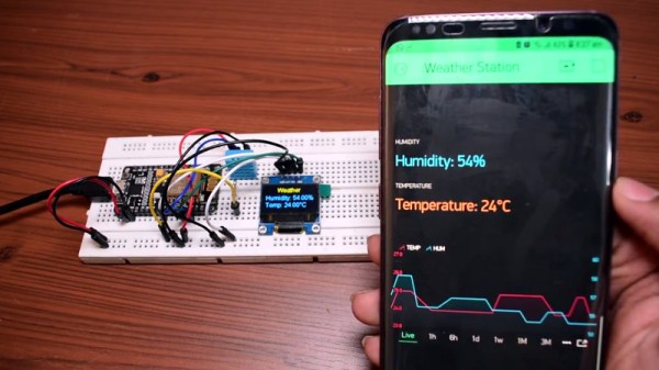
This simple indoor temperature and humidity sensor put together by [Shyam Ravi] shows one possible solution to the problem using Blynk. In the video after the break, he first walks you through wiring the demonstration hardware, and then moves on to creating the Blynk interface. While it might not be the ideal solution for all applications, it does show you how quickly you can go from a handful of components on the bench to displaying useful data.

In addition to the NodeMCU board, [Shyam] adds a DHT11 sensor and SSD1306 OLED display. He’s provided a wiring diagram in the repository along with the Arduino code for the ESP8266, but the hardware side of this demonstration really isn’t that important. You could omit the OLED or switch over to something like a BME280 sensor if you wanted to. The real trick is in the software.

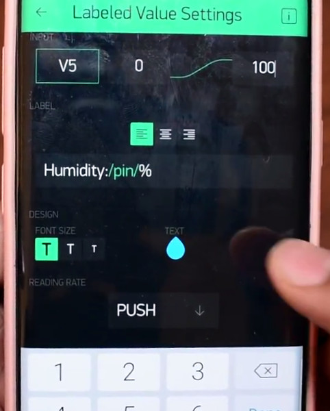
For readers who haven’t played with it before, Blynk is a service that allows you to create GUIs to interact with microcontrollers from anywhere in the world. The code provided by [Shyam] reads the humidity and temperature data from the DHT11 sensor, and “writes” it to the Blynk service. From within the application, you can then visualize that data in a number of ways using the simple drag-and-drop interface.

We’ve seen Blynk and ESP8266 used to control everything from mood lighting to clearance-rack robotic toys. It’s a powerful combination, and something to keep in mind next time you need to knock something together in short order.

Continue reading “Simple ESP8266 Weather Station Using Blynk”

What’s Behind The Door? An IoT Light Switch

We’re not sure who designed [Max Glenister]’s place, but they had some strange ideas about interior door positioning. The door to his office is right next to a corner, yet it opens into the room instead of toward the wall. Well, that issue’s been taken care of. But the architect and the electrician got the last laugh, because now the light switch is blocked by the open door.

Folks, this is the stuff that IoT is made for. [Max] here solved one problem, and another sprang up in its place. What better reason for your maiden voyage into the cloud than a terrible inconvenience? He studied up on IoT servo-controlled light switching, but found that most of the precedent deals with protruding American switches rather than the rockers that light up the UK. [Max] got what he needed, though. Now he controls the light with a simple software slider on his phone. It uses the Blynk platform to send servo rotation commands to a NodeMCU, which moves the servo horn enough to work the switch. It’s simple, non-intrusive, and it doesn’t involve messing with mains electricity.

His plan was to design a new light switch cover with mounting brackets for the board and servo that screws into the existing holes. That worked out pretty well, but the weight of the beefy servo forced [Max] to use a bit of Gorilla tape for support. He’s currently dreaming up ways to make the next version easily detachable.

Got those protruding American switches? [Suyash] shed light on that problem a while back.

Programmable Badge Uses E-Ink And ESP8266

You’ve probably noticed that the hacker world is somewhat enamored with overly complex electronic event badges. Somewhere along the line, we went from using a piece of laminated paper on a lanyard to custom designed gadgets that pack in enough hardware that they could have passed for PDAs not that long ago. But what if there was a way to combine this love for weighing down one’s neck with silicon jewelry and the old school “Hello my name is…” stickers?

[Squaro Engineering] might have the solution with Badgy, their multi-function e-ink name…well, badge. Compatible with the Arduino SDK, it can serve as anything from a weather display to a remote for your smart home. Oh, and we suppose in an absolute emergency it could be used to avoid having to awkwardly introduce yourself to strangers.

Powered by an ESP-12F, Badgy features a 2.9″ 296×128 E-Ink display and a five-way tactical switch for user input. The default firmware includes support for WiFiManager and OTA updates to make uploading your own binaries as easy as possible, and a number of example Sketches are provided to show you the ropes. Powered by a LIR2450 3.6 V lithium-ion rechargeable coin cell, it can run for up to 35 days in deep sleep or around 5 hours of heavy usage.

Schematics, source code, and a Bill of Materials are all available under the MIT license if you want to try your hand at building your own, and assembled badges are available on Tindie. While it might not be as impressive as a retro computer hanging around your neck, it definitely looks like an interesting platform to hack on.

Voltage Monitor Relay Is More Than Meets The Eye

Automotive components that have a hidden secondary function are usually limited to cartoons and Michael Bay movies, but this project that [Jesus Echavarria] created for a client is a perhaps as close as we’re likely to get in the near future. The final product certainly looks like a standard automotive relay, but a peek inside the 3D printed case reveals a surprisingly complex little device. It’s still technically a relay, but it uses a PIC microcontroller to decide when it should activate.

[Jesus] was given the task of creating a device that would fit into the relay box of a vehicle, and serve as a battery monitor to fire off at different voltage set points. The client also wanted the ability to configure such things as how long the device would wait before enabling and disabling the alarms once the voltage threshold has been passed. After showing the client an oversize prototype using a PIC16F88 and switching regulator, he got the OK to move on to a smaller and more cost-effective version.

The final hardware makes use of a 78M05 500 mA linear regulator, a PIC16F1824 microcontroller, and a pair of AQY211EH solid state relays. The standard five pin layout used for automotive relays allows the monitor to get power from the vehicle’s battery while providing two output channels that can be switched on and off from the microcontroller. [Jesus] says an agreement with the client prevents him from sharing some elements of the project (like the firmware source code), but he gives enough information that it shouldn’t be too hard to spin up your own version.

With the addition of something like an ESP8266, this could be an easy way to retrofit an older vehicle with “smart” features. As an example, it could potentially allow for controlling the car’s headlights and horn over Wi-Fi. Or you could hack together a theft deterrent system that refuses to power on the starter or fuel pump unless your smartphone enables the relay first.

ESP8266 Internet Controlled LED Dimmer

There’s no shortage of debate about the “Internet of Things”, largely centered on security and questions about how much anyone really needs to be able to turn on their porch light from the other side of the planet. But while many of us are still wrestling with the realistic application of IoT gadgets, there’s undoubtedly those among us who have found ways to put this technology to work for them.

One such IoT devotee is [Sasa Karanovic], who writes in to tell us about his very impressive custom IoT LED dimmer based on the ESP8266. Rather than rely on a commercial lighting controller, he’s designed his own hardware and software to meet his specific needs. With the LED strips now controllable by any device on his network, he’s started working on Python scripts which can detect what he’s doing on his computer and react accordingly. For example, if he’s watching a movie the lights will automatically dim, and come back up when he’s done.

[Sasa] has provided all the files necessary to follow in his footsteps, from the Gerber files for his PCB to the Arduino code he’s running on the ESP. The source code is especially worth checking out, as he’s worked in a lot of niceties that we don’t always see with DIY projects. From making sure the ESP8266 gets a resolvable DNS hostname on the network to using websockets which update all connected clients with status info in real-time, he’s really put a lot of work into making the experience as complete as possible.

He’s explains in his blog post what needs to be edited to put this code to work in your own environment, and there’s even some descriptive comments in the code and a helpful debug mode so you can see how everything works. It’s always a good idea to consider that somebody else down the road might be using your code; taking a few minutes to make things clear can save them hours of stumbling around in the dark.

If you need more inspiration for your ESP8266 lighting project, check out this ambient lighting controller for a kid’s room, or this professional under-cabinet lighting controller.

Grbl Ported To The ESP32

If you’re building a CNC or laser, there’s an excellent chance you’ll be using Grbl to get moving. It’s also a pretty safe bet you’d end up running it on some variation of the Arduino sitting in a motor controller breakout board. It’s cheap, easy to setup and use, and effectively the “industry” standard for DIY machines so there’s no shortage of information out there. What’s not to love?

Well, quite a few things in fact. As [bdring] explains, Grbl pushes the capability of the Arduino to the very limit; making it something of a dead-end for future development. Plus the Arduino needs to be plugged into the host computer via USB to function, a rather quaint idea to many in 2018. These were just some of the reasons he decided to port Grbl to the ESP32 board.

Price wise the Arduino and ESP32 are around the same, but the ESP does have the advantage of being much more powerful than the 8-bit Italian Stallion. Its got way more flash and RAM as well, and perhaps most importantly, includes Wi-Fi and Bluetooth out of the box. It still needs to be plugged into a board to hold the motor drivers like the Arduino, but beyond that [bdring] opines the ESP32 is about as close to the perfect Grbl platform as you can get.

[bdring] reports that porting the code over to the ESP32 wasn’t terrible, but it wasn’t exactly a walk in the park either. The bulk of the code went by without too much trouble, but when it came to the parts that needed precise timing things got tricky. The ESP32 makes use of a Real Time Operating System (RTOS) that’s not too happy about giving up control of the hardware. Turning off the RTOS was an option, but that would nuke Bluetooth and Wi-Fi so obviously not an ideal solution. Eventually he figured out how to get interrupts more or less playing nicely with the RTOS, but mentions there’s still some more work to be done before he’s ready to release the firmware to the public.

If you’ve been browsing Hackaday for a while you may remember [bdring]. He’s got a real knack for making things move, and has created a number of fantastic little CNC machines recently which have definitely caught our eye.

[Thanks to Jon and Craig for the tip.]

Continue reading “Grbl Ported To The ESP32”

ESP8266 Zelda Heart Responds To Tweets

It might not be enough to make you the Hero of Time, but this piece of Hylian interactive art would still be a worthy addition to your game room. [Jeremy Cook] writes in to tell us about how he put together this 8-bit style heart display, and goes into enough detail on the hardware and software sides of things that you shouldn’t have any problem adapting his design for your own purposes.

The build is pretty simple overall but it does assume you have a CNC to cut the basic shape out of MDF. You could cut the shape by hand if you had to, but if you don’t have a CNC the next best thing might be to 3D print the case. You’d potentially have to print it in two parts right down the center though, depending on how big your bed is. Whichever way you create the case, you’ll then need to cut the shape out of a piece of acrylic to make the face.

In any event, once the pieces are cut out [Jeremy] adds in a Wemos D1 Mini, a power supply, and some red LED strips. He provides a wiring diagram, but it’s fairly straightforward stuff. With a couple of 2N2222 transistors he controls the LED strips right from the digital pins of the ESP8266.

The software side is setup to be controlled via IFTTT by way of Adafruit.io. When IFTTT sees one of the keywords on Twitter, it passes a message to Adafruit.io which ultimately talks to the ESP8266 and gets the heart going. The software supports three states (on, off, and half) and gives a good example of a basic IoT implementation on the ESP8266 if you’re looking for some inspiration.

This hack seems like it would fit in perfectly with the Zelda home automation project we covered last year.