Kansas City Maker Faire: Lawn Da Vinci Is The Droid You’re Looking For

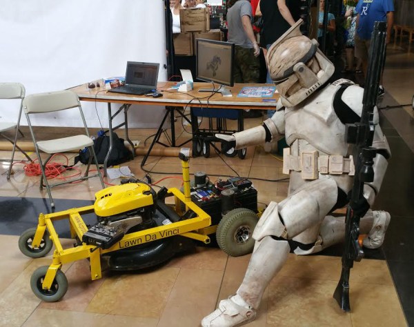
Summer is now in full swing, which means that mowing the lawn once a week is starting to get old. So why not build a robot do it for you? That’s what [Blake Hodgson] did, and he’s never been happier. It only took him a couple of weeks of quality time at one of the local makerspaces.

[Blake] was showing off Lawn da Vinci at this year’s Kansas City Maker Faire. He had his own booth around the corner from Hammerspace, the shop where it all came together. [Blake] started with a standard push mower from a garage sale and designed a frame around it using OnShape. The frame is made from angle iron, so it’s strong enough that he can ride on the thing. To each his own, we say. The wheels and motors came from a mobility scooter and match the beefiness of the frame. These are powered by two 12v car batteries wired in series. He drives it around his yard with an R/C airplane controller.

lawnmower guts
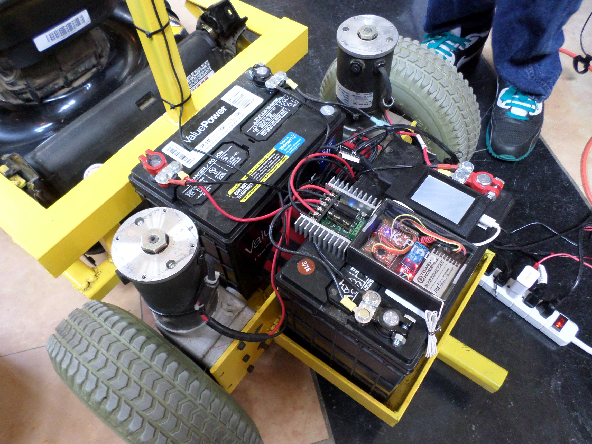
Lawn da Vinci’s brainpower comes from two Arduino Pro Minis and a Raspberry Pi. One Arduino controls the motors and the R/C signal from the remoteThe other runs some extra kill switches that keep the Lawn da Vinci out of trouble.

So what’s the Raspi for? Right now, it’s for streaming video from the webcam attached to a mast on the frame back to his phone. [Blake] says he has had some latency issues with the webcam, so there could be a pair of drone racing goggles in his future. He also plans to add a GPS logger and to automate part of the mowing.

Now, about those kill switches: there are several of them. You probably can’t have too many of these on a remote control spinning suburban death machine. Lawn da Vinci will stop grazing if it goes out of range of the remote or if the remote is turned off. [Blake] also wired up a dedicated kill switch to a button on the remote and a fourth one on a separate key fob.

The Lawn da Vinci is one of many example projects that [Blake] uses to showcase the possibilities of KC Proto, a company he started to help local businesses realize their ideas by offering design solutions and assistance with prototyping. Between mowings, [Blake] puts the batteries on a trickle charger. If you make your own robot lawn mower, you might consider building a gas and solar hybrid.

Micropython Binaries For The ESP8266 To Be Released

MicroPython is a Kickstarted project that brings Python to small, embeddable devices. As part of the terms of the Kickstarter, supporters were to get exclusive access to binary builds, with a few exceptions. Now it looks like the ESP8266-version is going to be added to the binary list. This is awesome news for anyone who enjoys playing around with the popular WiFi chip.

But even more heartwarming is the overwhelming response of the Kickstarter’s backers for making the binary builds public. Basically everyone was in favor of opening the binaries up to the general public, and many wrote that they wanted public binaries all along. People can be so giving.

But there’s also something in it for them! The more people get behind MicroPython, the more (free and paid) development support it will warrant, and the more bug reports it will garner. Wins all around. So keep clicking refresh on the binary list until you see it live. Or better yet, if you’re interested, head over to the forum. (Or just wait for us to cover it here. You know we will.)

Kansas City Maker Faire: Pi-Plates

As soon as he spied the Jolly Wrencher on my shirt, [Jerry Wasinger] beckoned me toward his booth at Kansas City Maker Faire. Honestly, though, I was already drawn in. [Jerry] had set up some interactive displays that demonstrate the virtues of his Pi-Plates—Raspberry Pi expansion boards that follow the HAT spec and are compatible with all flavors of Pi without following the HAT spec. Why not? Because it doesn’t allow for stacking the boards.

[Jerry] has developed three types of Pi-Plates to date. There’s a relay controller with seven slots, a data acquisition and controller combo board, and a motor controller that can handle two steppers or up to four DC motors. The main image shows the data acquisition board controlling a fan and some lights while it gathers distance sensor data and takes the temperature of the Faire.

The best part about these boards is that you can stack them and use up to eight of any one type. For the motor controller, that’s 16 steppers or 32 DC motors. But wait, there’s more: you can still stack up to eight each of the other two kinds of boards and put them in any order you want. That means you could run all those motors and simultaneously control several voltages or gather a lot of data points with a single Pi.

The Pi-Plates are available from [Jerry]’s site, both singly and in kits that include an acrylic base plate, a proto plate, and all the hardware and standoffs needed to stack everything together.

Cute USART Trick Brings PWM To IR LEDs

We love little tricks like this. Suppose that you want to generate an IR remote’s signal. It’s easy, because most of the codes are known. But it can be slightly harder because most IR remotes and receivers modulate the on pulses with a square wave at roughly 38 kHz for background lighting immunity.

With a competent PWM generator on a microcontroller, you can create this carrier modulation easily enough yourself. Set the PWM frequency to 38 kHz and the duty cycle somewhere in the 33%-50% range, and you’re set. But what if you don’t have a competent PWM generator? Such was the case that prompted [AnalysIR Blog] to fake it, with USART.

Here’s the trick. You set up the serial port to communicate at ten times the desired carrier frequency, and then transmit “special” data. (The number ten comes from eight bits of data plus a start and a stop bit.) If you want a 50% duty cycle, you simply send 0b11110000, as fast as the microcontroller will allow, for a mark and nothing for a space.

There’s some extra detail with inverting the signal if, as most do, your USART idles high. But that’s really it. It’s a cute trick for when you’re desperate enough to need it. And if you’d like to brush up some more on your asynchronous serial skills, check out our guide on troubleshooting USART, and the great comments that ensued.

Hackaday Prize Entry: A Minimal ATtiny Voltage And Frequency Counter

Sometimes when you build something it is because you have set out with a clear idea or specification in mind, but it’s not always that way. Take [kodera2t]’s project, he set out to master the ATtiny series of microcontrollers and started with simple LED flashers, but arrived eventually at something rather useful. An ATtiny10 DVM and DFM all-in-one with an i2c LCD display and a minimum of other components.

The DFM uses the ATtiny’s internal 16 bit timer, which has the convenient property of being able to be driven by an external clock. The frequency to be measured drives the timer, and the time it returns is compared to the system clock. It’s not the finest of frequency counters, depending as it does on the ATtiny’s clock rather than a calibrated crystal reference, but it does the job.

The results are shown in the video below, and all the code has been posted in his GitHub repository. We can see that there is the basis of a handy little instrument in this circuit, though with the price of cheap multimeters being so low even a circuit this minimal would struggle to compete on cost.

Continue reading “Hackaday Prize Entry: A Minimal ATtiny Voltage And Frequency Counter”

Serially, Are You Syncing Or Asyncing?

I know you’ve heard of both synchronous and asynchronous communications. But do you really know the differences between the two?

Serial communication was used long before computers existed. A predecessor is the telegraph system using Morse Code, one of the first digital modes of communication. Another predecessor is the teletype, which set standards that are still used today in your Arduino or Raspberry Pi.

All you need is two wires for serial communications, which makes it simple and relatively robust. One wire is ground and the other the signal. By interrupting the power with predefined patterns, information can be transferred over both short and long distances. The challenge is receiving the patterns correctly and quickly enough to be useful.

I was a bit surprised to find out the serial port on the Arduino Uno’s ATmega328P microcontroller is a Universal Synchronous Asynchronous Transmitter Receiver (USART). I’d assumed it was only a UART (same name, just leave out synchronous) probably because my first work with serial communications was with the venerable Intel 8251 “Programmable Communication Interface”, a UART, and I didn’t expect the microcontroller to be more advanced. Silly me. Later I worked with the Zilog 8530 Serial Controller Chip, a USART, the term I’ll use for both device types.

All these devices function in the same way. You send a byte by loading it into a register and it is shifted out one bit at a time on the transmit (TX) line as pulses. The receiver accepts the pulses on a receive (RX) input and shifts them into a register, which is then read by the system. The transmitter’s job is pretty easy it just shifts out the bits at a known clock rate. The receiver’s task is more complex because it needs to know when to sample the incoming signal. How it does this is the difference between asynchronous and synchronous communications.

Continue reading “Serially, Are You Syncing Or Asyncing?”

AVR Vs PIC, Round 223: Fight!

Get ready to rumble! [Thierry] made the exact same Hello-World-esque project with two microcontrollers (that are now technically produced by the same firm!) to see how the experience went.

It’s not just an LED-blinker, though. He added in a light-detection function so that it only switches on at night. It uses the Forest Mims trick of reverse-biasing the LED and waiting for it to discharge its internal capacitance. The point is, however, that it gives the chip something to do instead of simply sleeping.

Although he’s an AVR user by habit, [Thierry] finds in favor of the PIC because it’s got a lower power draw both when idling and when awake and doing some computation. This is largely because the PIC has an onboard low-power oscillator that lets it limp along at 32 kHz, but also because the chip has a lower power consumption in general. In the end, it’s probably a 10% advantage to the PIC on power.

If you’re competent with one of the two chips, but not the other, his two versions of the same code would be a great way to start familiarizing yourself with the other. We really like his isDarkerThan() function which makes extensive use of sleep modes on both chips during the LED’s discharge period. And honestly, at this level the code for the two is more similar than different.

(Oh, and did you notice [Thierry]’s use of a paper clip as a coin-cell holder? It’s a hack!)

Surprisingly, we’ve managed to avoid taking a stray bullet from the crossfire that occasionally breaks out between the PIC and AVR fans. We have covered a “shootout” before, and PIC won that round too, although it was similarly close. Will the Microchip purchase of Atmel calm the flames? Let’s find out in the comment section. We have our popcorn ready!