Tricking The BeagleBone Into Outputting Video

[FlorianH] wanted to get video out working with his BeagleBone but he just couldn’t figure out how to make the kernel play ball. Then a bit of inspiration struck. He knew that if you plug in the official DVI cape (that’s the BeagleBone word for what you may know as a shield) the kernel automatically starts pumping out the signals he needs. So he figured out a way to spoof the cape and output video.

At boot time the kernel polls the I2C bus to see what’s connected. The DVI cape has an EEPROM which identifies it. Since the data from the EEPROM is available for download [FlorianH] grabbed the data he needed, then used an ATmega32 to stand in for the memory chip. When he got the chip talking to the BeagleBone he was able to detect the video sync signals on his scope and he knew he was in business.

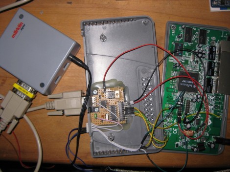
Look closely at the breadboard on the right. We love that SIL breakout board for the ATmega32. Very prototype friendly!

Playing Video On An 8-bit Microcontroller

The LCD displays for Nokia phones have seen a ton of use as easily interfaced displays for Arduino or other microcontroller projects. Usually, these LCDs are only used for displaying a few lines of text, or if someone is feeling really fancy, a small graph. Shame, then that we don’t see more complicated and computationally difficult tasks like playing video very often. [Vinod] sent us his way of playing video on these small color screens, surprisingly using only an ATMega32 microprocessor.

The build started off by saving uncompressed image data on an SD card using code from a previous project. [Vinod] was able to write a slideshow program to go through the SD card one file at a time and displaying each image. From there, it was simply a matter of using a Python script to convert frames of an .AVI video file to an uncompressed image and display them at 15 frames/second.

Turning these videos into talkies was a bit of a problem, but after taking an uncompressed .WAV file and sending that to a PWM pin on the ATMega, [Vinod] managed to play sound alongside his video.

The result is the ability to play a video with sound at 15 frames a second and a 132 x 65 resolution. You can check out the demo video after the break.

Continue reading “Playing Video On An 8-bit Microcontroller”

Parallax Shows Love For Open Source: GCC + Propeller

Parallax has done something that is unthinkable for most microcontroller manufacturing companies. They’ve decided to throw their support behind an open source toolchain based on GCC. That’s right, instead of fighting to get your code compiling on a platform whose example code uses crippleware, you can actually download, compile, and start using this toolchain without code size restrictions or other unfavorable limitations.

Why does this matter? One example that comes to mind is ChibiOS and the STM32F0-Discovery board. We’ve been playing around with that board recently and found out that the Atollic 8k code-size limitation prevents you from debugging ChibiOS. So you either pony up the registration fee, or go though at least a little pain (a lot depending on your skill level) to move to an open source solution. Here that’s not going to happen because you start with a GCC option from the word ‘Go’.

So join us in a round of applause for good decisions. Bravo Parallax! This Beta test targets the P8X32A Propeller chip but we hope it’s so popular that the rest of the line gets its own support.

[Thanks Devlin via Adafruit]

Multi-channel Analog Input Module Is A Good Jumping-off Point For Many Projects

[Scott Harden] has already produced some projects which measure analog inputs. But he’s got plans for more and wanted a base system for graphing analog signals. You can see the small board next to his laptop which offers the ability to sample up to six signals and push them to a PC via USB.

The ATmega48 and a few supporting components are all you’ll find on that board. The USB connection is taken care of by an FTDI cable. He went that route because the cables are relatively cheap, easy to come by, and already have driver support on all the major operating systems. If you look at the screen you can see a window graphing one analog input in real-time. He wrote this in Python (which is once again a cross-platform tool) and it has no problem graphing all six inputs at once.

This is immediately useful as an upgrade to [Scott’s] ECG machine. His future plans include a Pulse Oximeter, EEG, and EEG.

Driving A PSP Screen With An FPGA

Here’s [FlorianH’s] setup for driving a PlayStation Portable screen with an FPGA. He’s using the DE0-Nano board to do this, and the first order of business was to establish a way to connect the two. He did a great job of etching his own breakout board, which has some traces that are less than 10 mils thick. Soldering the connectors for the screen was a bit of a challenge, and he shared several pictures of the process for your enjoyment.

With everything hooked up he fired it up with just a couple of lines of code to draw a test pattern. From there it was on to building a more intensive driver. [FlorianH] mentioned to us that he’s just starting to learn about FPGAs after having worked extensively with 8-bit microcontrollers. He’s been documenting his work on his site, and finds himself frequently referencing his own material so remember how he did things. Our vicarious enjoyment is an unintended (but welcomed) consequence of that habit.

Router Controlling Choo-choos Over The CAN Bus

This setup is used to control a model railroad. Well, not entirely this setup. [Gerhard Bertelsmann] already has a proper railroad controller, and it just happens to offer CAN bus communications. He’s using OpenWRT and a cheap router to connect the bus to the network.

Originally he wanted to use a Raspberry Pi board for the project, but the incredible backorder  situation with that hardware led him to grab an old router. After loading OpenWRT he started working out how to connect a couple of ICs (MCP2515 and MCP2551) that will take care of the CAN bus communications. The hardware connections end up being pretty simple, with five data lines (and their pull-up resistors) connecting to the router’s serial header. From there it was a matter of mapping the device in software so that the hardware can be controlled over the network.

We like this example since CAN is used is a lot of other applications.

Template For Building STM32F0-Discovery Project In GCC

Yep, that blue light is blinking and I made it happen. I’ve been hard at work since I got my free STM32F0-Discovery board in the mail. Most recently I put together a starting template for building STM32F05x project on Linux. You’ll still need to install your own tool chain (I’m using the Code Sourcery G++: Lite Edition), but this makes it a snap to compile your projects with support for STM’s peripheral libraries.

As for programming, you may remember that I added support for writing to RAM in the stlink project. I’ve wasted spent a ton of time trying to get support for writing to Flash into that project. It’s just less of a hassle to use stlink than it is to work with OpenOCD. But I’ve really hit a wall getting the flash loader code to work. If you want to check out what I’ve done so far in that area I committed a very messy branch (see the commits for what code changes I’ve made).

In the mean time you can use OpenOCD to write images compiled with the template to your device. I included the ‘make program’ option in the Makefile to do this from command line. If you need help compiling OpenOCD check the readme in the template repository.